Which Breadboard Components Do You Really Need for Fast Electronics Prototyping?
Why Do Breadboard Components Matter in Real Prototyping?
Breadboard components decide whether your prototype acts like a circuit you can test or a loose pile of parts that keeps wasting time. If you build test circuits for LEDs, sensors, timers, microcontrollers, or small control boards, the right parts help you work faster and avoid common wiring mistakes. For more electronic parts guides, you can also browse the Components section. A breadboard is only the base. The real work comes from the jumpers, resistors, capacitors, switches, ICs, modules, and power parts you put on it.
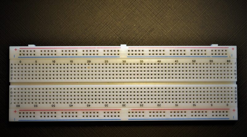
A common solderless breadboard uses rows of spring contacts under the plastic holes. Most standard boards follow a 0.1 inch, or 2.54 mm, grid, which matches DIP ICs, pin headers, jumper wires, and many development boards. That spacing is the reason you can move a circuit from a rough sketch to a working test in a short time. Sources such as DigiKey maker tutorials and Raspberry Pi educational material describe breadboards as temporary wiring platforms for learning, testing, and debugging small circuits. That is the point to keep in mind: breadboards are for quick trials, not final high-current products.
Faster Testing Before Soldering
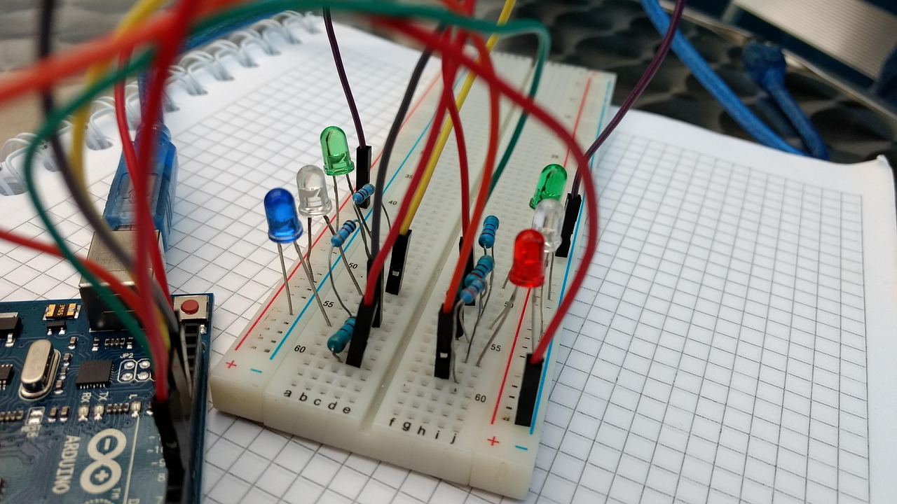
You can change a resistor value, move a sensor pin, or add a pull-down resistor without cutting traces. That matters when the design is still being checked on the bench. For example, an LED circuit may start with a 220 ohm resistor, then move to 330 ohms for lower brightness and less current. There is no board spin, no solder wick, and no wasted afternoon over one small value.
Lower Risk During Circuit Learning
Beginners often reverse LED polarity, forget a ground line, or place an IC across the wrong rows. A breadboard makes those mistakes easier to spot and correct. Still, low risk does not mean no risk. A short between 5 V and ground can heat wires fast, especially when the supply comes from a strong USB port or bench supply.
Cleaner Paths for Debugging
Good breadboard work gives each signal a path you can follow with your eyes. When a button input floats, a sensor gives strange readings, or a microcontroller resets, tidy wiring makes the fault easier to find. It is not exciting work, but it saves time. A neat board often beats a neat schematic that nobody can trace in the real build.
Which Basic Breadboard Components Should You Keep First?
You do not need a large kit to start. A better first set includes parts that show up in most small circuits. These parts handle connection, current control, timing, logic input, visible feedback, and power distribution. Buy fewer types at first, but choose values you will actually use.
Jumper Wires and Solid Core Wire
Jumper wires are the breadboard components you will use most. Male-to-male jumpers connect two breadboard rows, while male-to-female jumpers connect a breadboard to a sensor module, display, or development board. Female-to-female wires help when you work with pin headers. Many breadboard tutorials from suppliers such as DigiKey describe jumper wires as the basic conductive links for solderless prototyping. In day-to-day work, solid core 22 AWG wire is also useful because it stays flat and can be cut to the length you need.
- Use short wires for nearby rows, especially ground and signal lines.
- Use color habits: red for positive supply, black or blue for ground, yellow or green for signals.
- Avoid long wire loops on analog sensor circuits because they can pick up noise.
Resistors for Current and Logic States
Resistors protect LEDs, set timing with capacitors, divide voltage, and create pull-up or pull-down states. A small working box should include 220 ohm, 330 ohm, 1 k ohm, 4.7 k ohm, 10 k ohm, and 100 k ohm values. The 10 k ohm resistor is a usual choice for button pull-ups and pull-downs. For LED tests on 5 V logic, 220 ohm to 1 k ohm is common, depending on brightness and LED type.
LEDs, Diodes, and Simple Indicators
LEDs are not just for looks. They show power status, signal state, boot state, or pulse activity. A diode can help protect against reverse current in simple relay and motor circuits. Keep red, green, and blue LEDs, plus common signal diodes such as 1N4148 and rectifier diodes such as 1N4007. A small indicator LED on a breadboard can save several minutes of checking with a multimeter.
How Should You Choose Power Components for a Breadboard?
Power is where many breadboard problems start. A stable prototype needs the right voltage, enough current, shared ground, and safe limits. A solderless breadboard is not built for heavy loads. Motors, heaters, LED strips, and high-current relays should not draw large current through the breadboard contact strips.
5 V and 3.3 V Supply Rails
Many Arduino-style circuits use 5 V logic, while Raspberry Pi Pico and many current sensor boards use 3.3 V logic. Arduino documentation for the UNO R3 lists a 5 V operating voltage, 14 digital input and output pins, and 6 analog inputs. Raspberry Pi Pico documentation describes Pico GPIO as fixed at 3.3 V. The practical rule is simple: do not connect a 5 V signal directly into a 3.3 V-only input unless the module says it can accept it.
Breadboard Power Modules
A breadboard power module can provide selectable 5 V and 3.3 V rails from USB or a DC input. It is convenient, but you still need to read the module label and avoid using it like a full bench supply. Low-cost modules may have limited current, poor regulation, or little useful protection. If a Wi-Fi module resets during transmit, the power rail may be dropping. At first it may look like bad code. Quite often, it is just power.
Decoupling Capacitors Near Active Parts
Capacitors help smooth sudden current demand. Place a 0.1 microfarad ceramic capacitor near the power pins of ICs and sensor modules when the circuit behaves in an unstable way. Add a larger electrolytic capacitor, such as 10 microfarads or 100 microfarads, across the supply rail when motors, buzzers, or wireless modules share the board. DigiKey educational material notes that electrolytic capacitors are polarized, so the positive and negative leads must face the right way. That small detail matters because a reversed electrolytic capacitor can fail very quickly.
Which Signal Components Make a Breadboard More Useful?
Signal parts turn a powered board into a circuit you can actually use and test. Buttons, potentiometers, sensors, and display parts let you check real inputs and visible outputs. This is where a breadboard becomes more than a wiring exercise.
Push Buttons and Tactile Switches
Push buttons are used for reset, mode selection, menu input, and user control. On a breadboard, many 6 mm tactile switches fit across the center gap. Pair a button with a 10 k ohm resistor, or use the microcontroller internal pull-up if the firmware supports it. If a button gives random readings, it may be floating or bouncing. Floating needs a defined resistor state, while bouncing needs code handling or a small hardware filter.
Potentiometers and Trimmers
A 10 k ohm potentiometer is a useful analog input source. You can simulate a sensor value, tune LED brightness, adjust a timer, or test an ADC channel. Arduino reference material states that many Arduino boards map analog input voltage to a 10-bit value from 0 to 1023, depending on the board reference voltage. In plain terms, turning the knob changes the voltage the controller reads.
Sensors and Breakout Modules
Temperature sensors, light sensors, Hall sensors, IMU boards, and I2C modules often come on breakout boards with 0.1 inch headers. Check three things before inserting one: supply voltage, logic level, and pin order. Some modules label pins as VCC, GND, SCL, and SDA. Others use VIN and 3V3. The names look close enough to rush past, but this is where parts can get hot if you wire them wrong.
What Active Components Belong in a Serious Breadboard Kit?
Active parts control, switch, amplify, regulate, and process signals. They make prototypes closer to real products. Start with a small selection that matches your projects instead of filling drawers with parts you may not identify later.
Transistors and MOSFETs
A microcontroller pin can drive logic, not heavy loads. Use a transistor or logic-level MOSFET to switch small motors, LED strips, solenoids, or relays. A 2N3904 or BC547 works for small signal switching. A logic-level N-channel MOSFET suits higher current loads, as long as the gate threshold and current rating fit the job. Add a flyback diode across inductive loads such as relay coils and small DC motors. See also: Gadgets.
Integrated Circuits in DIP Packages
DIP ICs fit breadboards well because their pins straddle the center gap. Useful examples include the NE555 timer, LM358 op amp, 74HC logic chips, shift registers, and optocouplers. Place the notch or dot in a consistent direction, then connect power before signals. Many faults come from one IC leg sitting one row off, which is annoying because it can cost half an hour before you notice it.
Microcontroller Boards and Headers
Arduino UNO, Nano-style boards, ESP32 development boards, and Raspberry Pi Pico boards often sit next to or directly on a breadboard. Header spacing matters. An Arduino UNO usually connects with jumper wires, while a Pico or Nano can plug into the board if headers are soldered. Use one common ground between the microcontroller and every external module. Without common ground, signals have no shared reference and readings become unreliable.
How Do You Avoid Common Breadboard Component Mistakes?
Most breadboard failures are simple. Wrong row, missing ground, reversed capacitor, no resistor, weak power, or a loose wire can all stop a test. The fix is not expensive equipment. It is a checking habit you repeat every time.
Row and Rail Confusion
On many breadboards, each group of five holes in a terminal strip is connected sideways. The center gap separates the two sides. Power rails run lengthwise, but some boards split each rail halfway. Use a multimeter continuity mode to check the rail before building. If your right side has power and your left side is dead, a split rail may be the reason.
Current Limits and Heat
Public tutorials often use LEDs, sensors, and logic chips because breadboards are suited to low-power circuits. For high-current loads, route current outside the breadboard with screw terminals, thicker wire, or a proper PCB. If a jumper feels warm, stop the test. Heat is not normal on a small breadboard circuit, and it means the current path needs to be checked.
Loose Leads and Worn Contacts
Thin component leads, old breadboard holes, and bent jumper pins can create faults that come and go. A circuit that works only when you touch the wire is not mysterious; it usually has a poor connection. Trim leads cleanly, avoid forcing oversized pins into holes, and retire boards that have lost spring tension. That is cheaper than chasing the same fault for another day.
How Can You Build a Practical Breadboard Components Starter Set?
A useful starter set should cover about 80 percent of simple prototypes: LED tests, sensor reading, button input, relay driving, timer circuits, and microcontroller demos. The set below keeps cost under control and avoids the usual beginner kit problem, where half the parts stay unused.
Core Passive Parts
Start with passive parts because they are used in almost every test circuit. Keep the values simple, label the bags clearly, and replace the common values before they run out.
- Resistors: 220 ohm, 330 ohm, 1 k ohm, 4.7 k ohm, 10 k ohm, 100 k ohm
- Capacitors: 0.1 microfarad ceramic, 1 microfarad ceramic, 10 microfarad electrolytic, 100 microfarad electrolytic
- LEDs: red, green, yellow, and blue in 3 mm or 5 mm sizes
- Diodes: 1N4148 signal diodes and 1N4007 rectifier diodes
Useful Control and Interface Parts
Control and interface parts let you test how a user or sensor will interact with the circuit. These items are low cost, but they save time when you need a quick input, adjustment, or connection point.
- 6 mm tactile switches and small slide switches
- 10 k ohm potentiometers and small trimmers
- Male header pins, female headers, and screw terminal breakout boards
- Basic sensors for light, temperature, and magnetic detection
Active and Power Parts
Active and power parts should be chosen around the loads you expect to switch or control. Do not buy too many versions at first; a few known parts are easier to test, stock, and reorder.
- Small NPN transistors and logic-level N-channel MOSFETs
- NE555 timers, LM358 op amps, and basic 74HC logic ICs
- 5 V and 3.3 V breadboard power modules
- Arduino-compatible or Pico-style microcontroller boards
For purchasing, check each part’s voltage rating, package type, lead pitch, and datasheet notes. Public documentation from Arduino, Raspberry Pi, and major electronics distributors gives enough verified data for common hobby and engineering prototypes. For some generic breadboard ratings, reliable public data can be hard to compare because many no-brand boards do not publish full contact resistance, rated current, or spring material. In that case, do not guess. Use the board for low-current testing only.
FAQ
Q1: What Are the Most Important Breadboard Components for Beginners? A: Start with jumper wires, resistors, LEDs, capacitors, push buttons, a 5 V or 3.3 V power source, and a basic microcontroller board. These parts cover most simple test circuits.
Q2: Can You Use Breadboard Components for Final Products? A: Usually no. Breadboards are best for temporary testing. Final products need soldered boards, connectors, proper mechanical support, and safer power routing.
Q3: Why Does a Breadboard Circuit Work Sometimes and Fail Later? A: The likely causes are loose wires, worn contacts, split power rails, weak power, or leads placed in the wrong row. Check continuity and rebuild the circuit in smaller sections.
Q4: Should You Choose 5 V or 3.3 V Breadboard Components? A: Match the voltage to your controller and modules. Arduino UNO R3 circuits often use 5 V logic, while Raspberry Pi Pico and many modern sensors use 3.3 V logic.
Q5: How Many Resistor Values Do You Need for Breadboard Work? A: Six values are enough for many prototypes: 220 ohm, 330 ohm, 1 k ohm, 4.7 k ohm, 10 k ohm, and 100 k ohm. Add more later when a project needs exact values.