Capacitor components explained for modern electronic design
What capacitor components do in a circuit
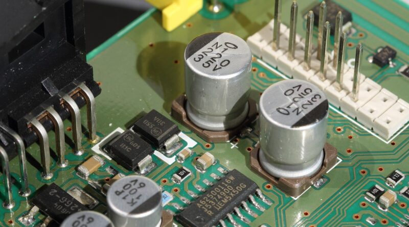
Capacitor components are passive electronic parts that store energy in an electric field and release it when the circuit needs it. In real designs, they are used for decoupling, filtering, timing, coupling, energy buffering, snubbing, power factor correction and signal conditioning. The right part is not selected by capacitance alone. Engineers also check dielectric material, voltage rating, temperature behavior, equivalent series resistance, ripple current capability, leakage current, package size, lifetime and safety approvals.
For readers browsing the broader Components category, capacitors are a good example of why passive parts still need careful specification. A 10 µF capacitor in a bill of materials can behave very differently depending on whether it is ceramic, aluminum electrolytic, tantalum, film or a supercapacitor. The application determines which trade-offs matter.
Main types of capacitor components
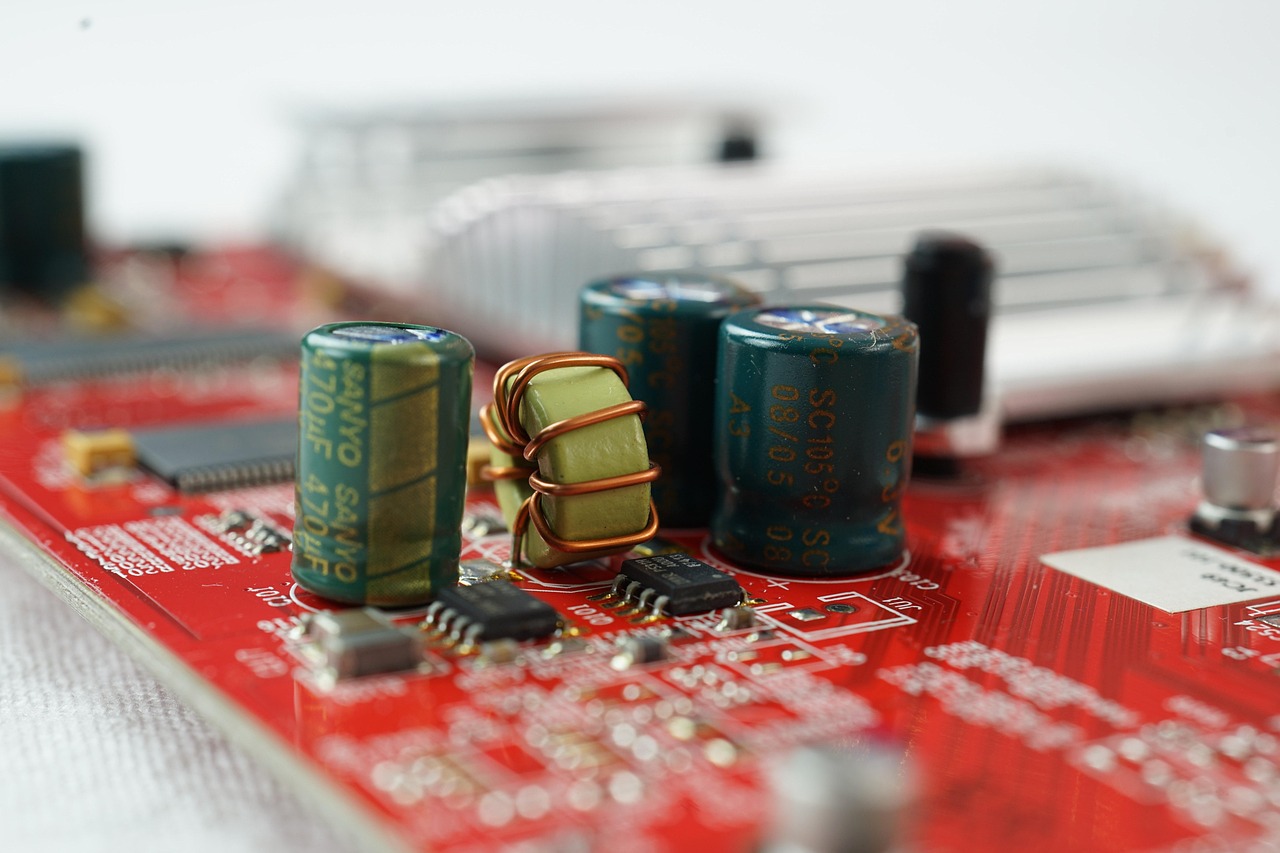
Capacitors are commonly grouped by dielectric or construction. Each family has a typical performance profile, although actual values vary by manufacturer, series and package size. Industry standards such as the IEC 60384 series describe fixed capacitor performance requirements, while automotive qualification is often evaluated against AEC-Q200. These references do not replace the component datasheet, but they help engineers and buyers understand how parts are categorized and tested.
Ceramic capacitors
Multilayer ceramic capacitors, often called MLCCs, are widely used for decoupling and high-frequency filtering. They are compact, available in surface-mount packages and cost-effective in many values. Class 1 ceramic dielectrics such as C0G or NP0 are valued for stability and low losses, which makes them suitable for precision timing, RF and resonant circuits. Class 2 dielectrics such as X7R and X5R provide higher capacitance per volume, but their effective capacitance can drop under DC bias, temperature change and aging.
Aluminum electrolytic capacitors
Aluminum electrolytic capacitors provide relatively high capacitance at moderate cost. They are common in power supplies, bulk energy storage, motor drives, LED drivers and industrial electronics. Their limitations include polarity, higher leakage than many ceramic or film capacitors, finite lifetime and performance changes with temperature. Datasheets typically specify endurance at a rated temperature, ripple current limits and expected life under defined conditions.
Tantalum and polymer capacitors
Tantalum capacitors offer high capacitance density and stable electrical behavior compared with many aluminum electrolytics. Traditional manganese dioxide tantalum capacitors require careful surge current control and voltage derating because failure can be severe if the part is overstressed. Polymer tantalum and aluminum polymer capacitors often provide lower ESR and improved ripple performance, but voltage, temperature and reliability guidance still need close review.
Film capacitors
Film capacitors use plastic film dielectrics such as polypropylene or polyester. They are widely selected where low loss, stability, high insulation resistance or AC performance matters. Typical applications include DC link circuits, EMI suppression, snubbers, audio signal paths, power factor correction and pulse circuits. Safety-rated film capacitors are also used across the line or from line to ground in mains-connected equipment, where the correct safety class is essential.
Supercapacitors
Supercapacitors, also called electric double-layer capacitors in many contexts, provide far higher capacitance than conventional capacitor families. The trade-offs are lower voltage per cell and higher leakage than many standard capacitors. They are used for short-term backup power, memory hold-up, peak current support and energy harvesting buffers. They are not direct replacements for rechargeable batteries or ordinary decoupling capacitors; their strength is rapid charge-discharge cycling over short energy-storage intervals.
Key specifications that matter more than capacitance alone
The capacitance value shown on a schematic is only the starting point. In operation, voltage, frequency, temperature and layout can change the result significantly. Good selection begins by identifying the electrical stress, then matching it to a capacitor family that can handle that stress with suitable margin.
| Specification | Why it matters | Design note |
|---|---|---|
| Rated voltage | Defines the maximum continuous voltage under specified conditions. | Use derating, especially for ceramics, tantalum and high-reliability designs. |
| Tolerance | Shows how far actual capacitance may vary from nominal value. | Critical in filters, oscillators, timing circuits and precision analog networks. |
| Temperature coefficient | Describes capacitance change over temperature. | C0G/NP0 ceramics and many film capacitors are more stable than high-capacitance Class 2 MLCCs. |
| ESR | Equivalent series resistance affects ripple heating, efficiency and transient response. | Low ESR is useful in power rails, but very low ESR can affect control-loop stability in some regulators. |
| ESL | Equivalent series inductance limits high-frequency effectiveness. | Package size, mounting style and PCB layout strongly influence high-frequency decoupling. |
| Leakage current | Represents unwanted current through the dielectric. | Important in battery-powered, timing, sample-and-hold and high-impedance circuits. |
| Ripple current | Indicates how much AC current the capacitor can handle without overheating. | Essential for electrolytic, polymer and film capacitors in power conversion. |
A common specification error is assuming that a capacitor’s nominal value is also its effective value in the circuit. A high-capacitance MLCC may be marked as 10 µF, yet deliver less effective capacitance under DC bias. An aluminum electrolytic may retain useful bulk capacitance, but its ESR and high-frequency behavior will differ from an MLCC. In many designs, the best answer is a combination of capacitor components rather than one universal part.
How capacitors are used in common electronic applications
Decoupling and bypassing
Decoupling capacitors provide local charge near integrated circuits and reduce supply rail noise. Small ceramic capacitors are commonly placed close to IC power pins because short current loops reduce parasitic inductance. Bulk capacitors are often placed nearby on the same rail to support lower-frequency load changes. Exact values depend on the IC, switching speed, PCB stack-up and power distribution network.
Power supply filtering
In AC-DC and DC-DC converters, capacitors smooth rectified waveforms, absorb ripple current and support transient loads. Aluminum electrolytic, polymer, ceramic and film capacitors may appear in the same supply for different roles. A bulk electrolytic can store energy, MLCCs can reduce high-frequency noise, and film capacitors may be selected for pulse or EMI functions.
Signal coupling and analog filtering
Capacitors can pass AC signals while blocking DC, forming coupling networks in audio, RF and sensor circuits. They also combine with resistors and inductors to create filters. In these applications, dielectric absorption, voltage coefficient, tolerance and temperature drift may matter more than small size. Precision circuits usually avoid high-K ceramic dielectrics in the signal path when distortion or capacitance variation would affect performance.
Motor, lighting and mains-connected circuits
Capacitors used around motors, lamps, grid-connected converters or mains inputs require particular care. Across-the-line and line-to-ground applications should use capacitors with the appropriate safety classification, often described as X or Y safety capacitors. Substituting an ordinary capacitor in a safety-critical location can create a fire, shock or compliance risk. See also: Gadgets.
Reliability, derating and failure modes
Capacitor failures can be gradual, intermittent or sudden. The most likely mechanism depends on construction and stress. Aluminum electrolytics can dry out over time, especially under high temperature and ripple current. Ceramic capacitors can crack from board flex, thermal shock or mechanical stress. Tantalum capacitors can fail under surge or reverse voltage. Film capacitors may self-heal after localized dielectric breakdown, but repeated stress still reduces design margin.
Derating means operating a component below its maximum rating to improve reliability. There is no single derating rule that fits every capacitor type. Ceramic capacitors need review for DC bias and temperature behavior. Tantalum capacitors often require conservative voltage derating and surge-current control. Electrolytic capacitors require thermal analysis because life is strongly affected by core temperature. Film capacitors used in pulse circuits require attention to dv/dt, peak current and RMS current.
Environmental and compliance requirements also affect capacitor selection. Equipment sold into regulated markets may need to consider substance restrictions such as RoHS, documentation expectations under REACH, flame-retardancy requirements, safety approvals or sector-specific qualification. These requirements should be checked against current product documentation rather than assumed from a generic capacitor type.
A practical selection workflow for engineers and buyers
A structured workflow reduces substitution errors and helps procurement teams understand which parameters are flexible and which are not. The following process is useful for early design reviews, alternate sourcing and component risk checks.
- Define the circuit function. Decide whether the capacitor is for decoupling, bulk storage, timing, filtering, coupling, snubbing, safety isolation or backup energy.
- Set electrical limits. Record working voltage, expected transients, ripple current, frequency range, allowable leakage and polarity.
- Check temperature and lifetime. Identify ambient temperature, self-heating, endurance requirement and expected operating hours.
- Choose a suitable capacitor family. Match the function to ceramic, electrolytic, polymer, tantalum, film or supercapacitor behavior.
- Review effective capacitance. For MLCCs, check DC bias curves. For electrolytics, check tolerance, temperature and aging effects.
- Validate package and layout constraints. Confirm footprint, height, vibration exposure, board flex risk and thermal placement.
- Confirm safety and qualification needs. Check whether the application requires AEC-Q200, IEC, UL, safety capacitor class or customer-specific approval.
- Control substitutions. Do not approve alternate parts based only on capacitance, voltage and package. Compare ESR, ripple, dielectric, lifetime and approvals.
For buyers, the key point is that capacitor alternates are not always drop-in replacements. A purchasing substitute may pass a basic parametric search while changing startup behavior, EMI margin, regulator stability or long-term reliability. Engineering review is especially important in power electronics, automotive, medical, aerospace, industrial control and mains-connected products.
Common mistakes when specifying capacitor components
- Ignoring DC bias in MLCCs. The installed capacitance may be much lower than the nominal value in high-voltage or small-case ceramic parts.
- Using capacitance as the only comparison point. ESR, ripple current, leakage, temperature and lifetime can be equally important.
- Replacing safety capacitors with ordinary parts. X and Y capacitor applications require suitable safety-rated components.
- Overlooking regulator stability. Some linear and switching regulators require a defined output capacitor ESR range or minimum capacitance.
- Forgetting polarity. Many electrolytic and tantalum capacitors are polarized and can fail if installed incorrectly.
- Underestimating thermal stress. Capacitor life can drop sharply when ripple heating and ambient temperature are not controlled.
- Assuming one technology is always better. Ceramic, film, polymer and electrolytic capacitors solve different design problems.
Frequently asked questions
What is the difference between a capacitor and a capacitor component?
In everyday electronics language, the terms often overlap. A capacitor is the electrical device that stores energy in an electric field. A capacitor component usually refers to the physical part selected, purchased and mounted in a circuit, including its package, rating, dielectric, tolerance and approvals.
Which capacitor type is best for decoupling?
MLCCs are commonly used for high-frequency decoupling because they are compact and have low parasitic resistance and inductance when properly placed. Power rails may also need bulk electrolytic, polymer or tantalum capacitors to support lower-frequency transients. The best choice depends on the IC, rail voltage, load profile and PCB layout.
Why do ceramic capacitors lose capacitance in operation?
Many high-capacitance ceramic capacitors use Class 2 dielectrics that are sensitive to DC bias, temperature and aging. As applied DC voltage increases, the effective capacitance can fall. Designers should check the manufacturer’s capacitance-versus-voltage data rather than relying only on the catalog value.
Are electrolytic capacitors still useful in modern designs?
Yes. Although MLCCs and polymer capacitors have replaced electrolytics in some compact designs, aluminum electrolytic capacitors remain useful for bulk energy storage, cost-sensitive power supplies and applications needing large capacitance values. Their lifetime, ripple current and temperature ratings must be evaluated carefully.
Can a higher voltage capacitor always replace a lower voltage one?
Not always. A higher voltage rating can provide more margin, but the replacement may have different size, ESR, leakage, dielectric behavior, capacitance under bias or safety approval. Any substitution should be checked against the circuit function and original design requirements.
Conclusion
Capacitor components look simple on a schematic, but their real performance depends on construction, dielectric behavior, electrical stress and operating environment. Ceramic capacitors are strong for compact high-frequency decoupling, electrolytics provide economical bulk capacitance, film capacitors support stable and safety-critical roles, tantalum and polymer capacitors offer density and low ESR options, and supercapacitors serve short-term energy storage needs. Reliable selection depends on the full datasheet, not just capacitance and voltage. That is the difference between a part that fits the footprint and a part that fits the design.