What Are Printed Circuit Board Components and How Do You Choose the Right Ones?
What Are Printed Circuit Board Components?
Printed circuit board components are the parts fitted on a PCB to make an electronic circuit work, from small resistors to connectors and power devices. If you are checking parts for a new product, the Components section is a practical place to begin because component choice affects cost, size, safety, repair, and service life. A board may look simple at first, but one wrong value, weak package, or poor sourcing choice can turn a clean design into a return problem later.
Passive Parts Set Basic Electrical Behavior
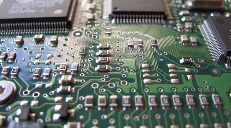
Resistors, capacitors, and inductors do not boost a signal on their own, but they set much of the board behavior. A resistor limits current, divides voltage, pulls a signal high or low, and helps set gain. A capacitor stores charge, filters noise, smooths power rails, and supports timing circuits. An inductor stores energy in a magnetic field, so it is common in switching power supplies and RF filters.
Active Parts Control Power and Signals
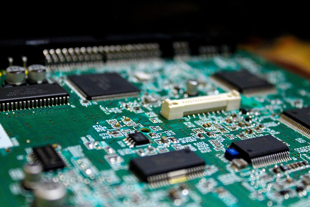
Active components include diodes, transistors, voltage regulators, logic ICs, microcontrollers, memory chips, sensors, and power management ICs. These parts switch, boost, regulate, calculate, sense, or protect. According to the WSTS Autumn 2025 semiconductor forecast, published in December 2025, the global semiconductor market was projected at about 772.2 billion USD in 2025 and 975.5 billion USD in 2026. This matters in daily design work because many PCB choices now depend on semiconductor availability, not only on the schematic.
Connectors and Mechanical Parts Finish the Product
Connectors, switches, relays, test points, fuse holders, headers, sockets, and shields are easy to overlook. They are the parts people touch, pull, plug, and sometimes damage in normal use. A USB-C connector on a handheld product, for example, may face thousands of insertion cycles, cable pull, dust, and bad plug-in angles. In many projects, a connector is the most mechanical electrical part on the board. It often needs more checking than it gets during early design.
Which Printed Circuit Board Components Matter Most in a Real Design?
Every board has a few components that bring more risk than the rest. A 1 percent feedback resistor, a battery charger IC, and a decorative LED should not receive the same review time. In practice, it is better to rank parts by electrical stress, heat, sourcing risk, safety function, and how hard they are to replace.
Power Components Carry the Highest Stress
Voltage regulators, MOSFETs, diodes, transformers, power inductors, current-sense resistors, and fuses often run hotter than logic parts. Check voltage margin, current rating, power dissipation, package thermal resistance, and the layout notes in the datasheet. A small SOT-23 regulator may pass the first calculation, then overheat when it sits near a warm processor with too little copper area. Heat does not always show up as a clear failure at the start, but it slowly cuts product life.
Signal Components Protect Data Quality
Clock crystals, impedance-matching resistors, RF filters, ESD arrays, common-mode chokes, and high-speed connectors affect signal quality. In USB, Ethernet, wireless, display, and sensor lines, placement can matter as much as the value. A part picked only for low cost can add capacitance, skew, or insertion loss, and that may hurt compliance testing later. For high-speed boards, review the component and its footprint together instead of treating them as separate tasks.
Safety Components Reduce Product-Level Risk
Fuses, varistors, TVS diodes, isolation components, optocouplers, safety capacitors, and protective resistors are not decoration. They help the product fail in a safer way when surge, overload, reverse polarity, or static discharge happens. Regulatory labs and customer auditors usually look at these parts closely. If a safety-rated capacitor is required, a normal ceramic capacitor with similar capacitance is not a proper substitute.
How Should You Choose Component Values and Packages?
Choosing component values is not just a calculation job. You also need to check package size, tolerance, temperature, supply chain, assembly yield, and service work. A component that works in a prototype can still be a poor fit for a 10,000-piece production run.
Electrical Ratings Need Real Margin
For resistors, check resistance, tolerance, power rating, voltage rating, and temperature coefficient. For capacitors, check capacitance, voltage, dielectric type, tolerance, aging, ripple current, and DC bias effect. A 10 µF MLCC may not behave like 10 µF under DC bias, especially in small packages. For diodes and MOSFETs, check current, voltage, thermal limits, gate charge, and switching loss. A simple shop-floor rule still works: read the worst-case conditions, not only the typical line.
Package Size Affects Assembly and Repair
Small packages save board space, but they can make assembly harder and rework slower. A 0402 resistor is common in modern SMT production, while 0201 parts need tighter process control and better inspection. BGA packages save routing area and support high pin count, but X-ray inspection may be needed to check solder joints. IPC-A-610 is widely used in the electronics industry for finished assembly acceptability, and IPC notes that it should be used together with IPC J-STD-001 for soldering requirements.
Temperature Range Must Match the Use Case
A consumer indoor board does not face the same conditions as a motor controller near a hot enclosure. Commercial, industrial, automotive, and military temperature grades exist because the working environment changes a lot. If the product sits in a sealed plastic housing under sunlight, the inside temperature can be far above room temperature. Choose components with enough headroom, and keep heat-sensitive parts away from power devices when the layout gives you room.
Why Does the BOM Control Your PCB Cost and Lead Time?
The bill of materials is not only a shopping list. It is a working control document for purchasing, engineering, quality, and manufacturing. A clear BOM helps you buy the right printed circuit board components, avoid unwanted substitutions, and keep production moving when supply gets tight.
Manufacturer Part Numbers Prevent Ambiguity
A BOM should include manufacturer name, manufacturer part number, value, tolerance, package, voltage or power rating, lifecycle status, approved alternates, and quantity per board. “10k resistor 0603” is not enough for many production jobs. If the design needs 0.1 percent tolerance or low temperature drift, that detail must be shown. If it is missing, purchasing may buy a cheaper part that looks close but does not meet the circuit target.
Lifecycle Status Protects Long-Term Builds
Components move through active, not recommended for new design, last-time-buy, and obsolete stages. If your product will be sold for five years, check lifecycle status before design release. This is especially important for microcontrollers, wireless modules, displays, and power ICs. Replacing a resistor is usually simple, but replacing a programmed IC with different pins, firmware tools, and regulatory impact is a much bigger job.
Market Data Shows Why Planning Matters
Component demand can move faster than a design schedule. The Global Electronics Association’s North American PCB statistical data for April 2026, reported by PCD&F in May 2026, showed PCB bookings up 25.5 percent year over year and a book-to-bill ratio of 1.24. That means orders were higher than shipments in that period. The point is not to buy in panic; it is to approve second sources early, confirm lead times before layout lock, and avoid rare parts unless they solve a real design problem. See also: Gadgets.
How Do Assembly Standards Affect Component Quality?
Good component selection still needs good assembly. Solder joints, component orientation, moisture control, cleanliness, and inspection rules decide whether the final PCBA is acceptable. A board can use the right parts and still fail because of tombstoned passives, lifted leads, cracked capacitors, or poor wetting.
IPC Classes Match Product Reliability Needs
IPC commonly groups electronic assemblies by end-use expectations. Class 1 covers general products where basic function is the main goal. Class 2 covers dedicated service electronics that need longer life and steady performance. Class 3 covers high-reliability products where downtime can be serious, such as medical, aerospace, defense, or critical industrial equipment. Choose the class based on the product and risk level, not just on the label that sounds highest.
Moisture Handling Protects Sensitive Packages
Many surface-mount ICs absorb moisture before reflow. During soldering, trapped moisture can expand and damage the package. IPC/JEDEC J-STD-020 defines moisture and reflow sensitivity classification for nonhermetic surface-mount devices, while J-STD-033 covers handling, packing, shipping, and use of moisture-sensitive parts. In factory terms, this means dry bags, humidity cards, floor-life tracking, and baking when the process calls for it.
Inspection Catches Visible and Hidden Defects
AOI can catch missing parts, wrong polarity, rotation errors, solder bridges, and many solder volume problems. X-ray inspection helps with hidden joints under BGAs, QFNs, and bottom-terminated components. Functional testing then checks whether the assembled circuit works as designed. The plain test points you add during design can save hours during debugging. They may not look important on the layout, but technicians are glad to have them when a board is dead at 5 p.m. on a Friday.
What Mistakes Should You Avoid When Selecting PCB Components?
Most component mistakes are not big engineering disasters. They are small misses that build up: a weak footprint, a vague BOM line, a part with no stock, or a capacitor with poor voltage behavior. Finding them early is cheaper than explaining them after production starts.
Ignoring Datasheet Footnotes Creates Surprises
Datasheet footnotes often show the real limits. They may explain thermal test conditions, derating curves, minimum load, startup behavior, recommended layout, or package differences. Do not stop at the headline rating on the first page. A MOSFET with low on-resistance may still run hot if the gate drive is weak. A regulator may need a specific output capacitor ESR range to stay stable.
Copying Reference Designs Without Context Adds Risk
Reference designs are useful, but they are built around a specific input voltage, load, board stack-up, enclosure, and compliance target. If your product changes the cable length, ambient temperature, load step, or board area, you may need different component ratings. Copying is common in electronics work, and there is nothing wrong with learning from a proven circuit. The risk starts when the design is copied without checking the new use case.
Choosing Rare Parts Can Slow Production
A rare part may look good in CAD, but it can create weeks of delay when stock disappears. For common resistors, capacitors, LEDs, and protection devices, choose widely available package sizes and values when performance allows it. For key ICs, check distributor stock, authorized channels, evaluation board support, firmware tools, and alternate pin-compatible options. A slightly larger package with steady supply can be the better business choice.
FAQ
Q1: What Are the Main Printed Circuit Board Components? A: The main components are resistors, capacitors, inductors, diodes, transistors, ICs, connectors, switches, relays, sensors, protection devices, and power parts. Each part type has its own job in signal control, power delivery, connection, or safety.
Q2: How Do You Choose the Right PCB Component Package? A: Match the package to board space, assembly capability, heat, current, inspection needs, and repair needs. Very small parts save area, but they may increase assembly cost and make rework harder.
Q3: Why Do Capacitors Fail or Perform Below Their Rated Value? A: Capacitors can lose effective capacitance because of DC bias, temperature, aging, ripple current, or the wrong dielectric choice. Always check the datasheet curves, not just the capacitance listed in the BOM.
Q4: What Standards Are Commonly Used for PCB Assembly Quality? A: IPC-A-610 is widely used for electronic assembly acceptability, and IPC J-STD-001 is commonly used for soldered electrical and electronic assembly requirements. IPC/JEDEC standards also guide moisture-sensitive component handling.
Q5: How Can You Reduce Component Sourcing Problems? A: Use clear manufacturer part numbers, approve alternates early, check lifecycle status, avoid rare parts when possible, and review lead times before final layout. A strong BOM often prevents more trouble than a late redesign can fix.