Basic components of electric circuit explained for beginners
What are the basic components of an electric circuit?
The basic components of electric circuit design are a power source, a conductive path, a load, a control element, and a protection element. In a simple flashlight, the battery supplies energy, metal conductors carry current, the lamp or LED converts electrical energy into light, the switch opens or closes the path, and protective design helps limit unsafe current or heat. More advanced circuits may add resistors, capacitors, inductors, diodes, transistors, sensors, connectors, fuses, and measurement points. The core principle is still the same: current needs a complete path, and every component should have a clear electrical purpose.
Understanding these parts is useful for students, hobbyists, technicians, and buyers comparing electronic assemblies. It also makes schematic diagrams easier to read and helps when diagnosing faults or selecting parts from a components catalog without confusing a part’s physical appearance with its electrical function.
The circuit source provides electrical energy
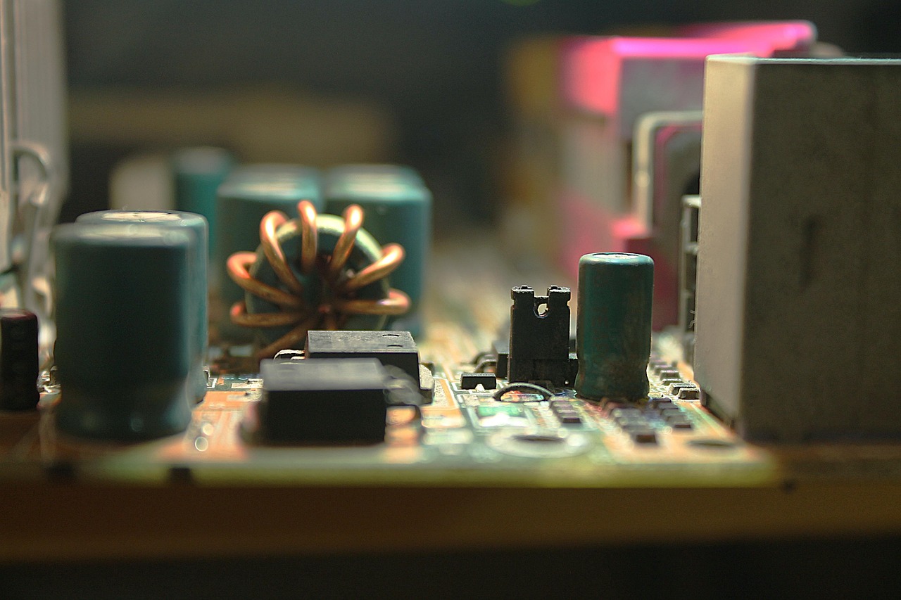
Every practical circuit needs an energy source. The source creates the voltage that can drive current through a closed path. Common examples include batteries, DC adapters, solar cells, bench power supplies, generators, and regulated power rails inside electronic equipment.
A source is usually described by voltage, current capacity, polarity, and whether it supplies direct current or alternating current. A small coin cell may be suitable for a low-power sensor, but not for a motor. A wall adapter may provide 5 V, 12 V, or another specified output, but its current rating still limits the load it can safely support.
In beginner circuits, the source is often treated as ideal, meaning it maintains its rated voltage regardless of what is connected. Real sources are not ideal. They have internal resistance, voltage tolerance, temperature limits, and safety restrictions. For that reason, a circuit should not be designed only by matching voltage labels. Expected current, operating environment, connector style, and protection method also matter.
DC and AC sources
Direct current flows with a fixed polarity, which makes it common in battery-powered electronics, microcontroller boards, sensors, and LED circuits. Alternating current changes direction periodically and is common in power distribution and many motor or transformer applications. The components around the source must match the source type. A capacitor, diode, switch, or fuse selected for a low-voltage DC project may not be suitable for mains AC power.
Conductors and connections complete the path
A conductor gives current a low-resistance path between circuit nodes. In a classroom diagram, that path may be shown as a plain line. In real equipment, it may be a copper wire, printed circuit board trace, terminal block, solder joint, connector pin, busbar, or cable assembly.
Good conductors are not only low in resistance. They also need to be mechanically secure, rated for the expected current, protected from corrosion, and routed to reduce the risk of accidental short circuits. A loose connector can behave like an intermittent switch. A thin trace carrying too much current can heat up. A damaged cable can expose conductive material and create a shock or fire risk.
Connections also define circuit topology. Series connections force the same current through multiple components. Parallel connections give components the same voltage across their terminals. Many beginner mistakes happen because a circuit looks connected physically but is not connected electrically in the intended way.
Ground is a reference, not always the earth
Many schematics use a ground symbol. In low-voltage electronics, ground often means the common reference point for measuring voltage, not necessarily a physical connection to earth. Confusing circuit ground with protective earth can lead to poor measurements and unsafe assumptions, especially when moving from battery circuits to mains-powered equipment.
Loads convert electrical energy into useful output
A load is the part of the circuit that uses electrical energy to do work. Lamps produce light, motors produce motion, heaters produce heat, speakers produce sound, and electronic modules process or communicate information. Even an integrated circuit can be considered a load from the point of view of the power supply feeding it.
Loads are defined by their voltage requirement, current draw, power rating, operating mode, and tolerance. For a resistive heater, power can often be estimated from voltage and resistance. For motors, current changes with starting load, speed, and mechanical resistance. For LEDs, current control is usually more important than simply applying a voltage.
A circuit becomes unreliable when the load demands more current than the source, conductors, or switching device can supply. It may also fail when the load creates electrical noise, voltage spikes, reverse-polarity stress, or heat that other components cannot tolerate. In practical design, the load is often considered first, then the source, wiring, control method, and protection are selected around it.
| Component role | Common examples | Main question to ask |
|---|---|---|
| Source | Battery, adapter, power supply | Can it provide the required voltage and current safely? |
| Conductor | Wire, PCB trace, connector | Can it carry the current with acceptable loss and heating? |
| Load | Lamp, motor, sensor module, IC | What output does it produce, and how much power does it need? |
| Control | Switch, relay, transistor, microcontroller output | How is current turned on, off, or adjusted? |
| Protection | Fuse, breaker, TVS diode, current limiter | What happens if a fault or overload occurs? |
Control components decide when and how current flows
Control components change the state or amount of current in a circuit. The simplest control part is a switch, which opens or closes the conductive path. Push buttons, toggle switches, rotary switches, relays, MOSFETs, bipolar transistors, and solid-state drivers all perform control functions, but they do so in different ways.
A manual switch is easy to understand because it physically separates or connects contacts. A relay uses an electromagnetic coil to move contacts, allowing a low-power signal to control a separate circuit. A transistor can switch or amplify current electronically without moving parts. In modern designs, a microcontroller often sends a logic signal to a transistor or driver IC, which then controls a load such as an LED strip, fan, pump, or actuator.
The control component must be rated for the circuit it controls. Contact voltage, current rating, switching speed, leakage current, heat dissipation, and isolation can all matter. A switch that works for a small indicator lamp may not be safe for a motor. A transistor that handles logic signals may fail when used to control a high-current load without proper heat management.
Open circuits and closed circuits
A closed circuit provides a complete path, so current can flow if a voltage source is present. An open circuit breaks that path, so current stops except for tiny leakage effects in some real components. Switches intentionally create open and closed states, while broken wires, cracked solder joints, and disconnected plugs create unintended open circuits.
Passive components shape voltage, current, and timing
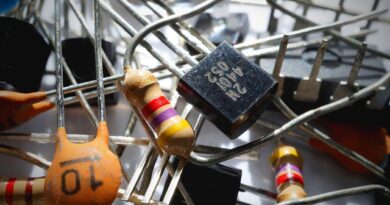
Passive components do not usually create energy or amplify a signal, but they strongly influence how a circuit behaves. The three classic passive components are resistors, capacitors, and inductors.
Resistors limit current and divide voltage
A resistor opposes current. In simple circuits, resistors are used to limit LED current, set bias conditions, divide voltage, discharge capacitors, and create predictable loads. Resistors are specified by resistance, tolerance, power rating, temperature coefficient, and package type. A resistor with the correct resistance but too low a power rating can overheat.
Capacitors store charge and smooth changes
A capacitor stores energy in an electric field. Capacitors are used for filtering, timing, decoupling, coupling signals, smoothing supply rails, and short-term energy storage. Important specifications include capacitance, voltage rating, dielectric type, equivalent series resistance, leakage, tolerance, polarity, and lifetime. Electrolytic capacitors are often polarized, while many ceramic capacitors are not. See also: Gadgets.
Inductors store energy in a magnetic field
An inductor resists rapid changes in current and stores energy in a magnetic field. Inductors appear in filters, switching power supplies, radio-frequency circuits, transformers, and motor-related designs. Their value, current rating, saturation behavior, winding resistance, and core material affect performance. In beginner projects, inductors are less visible than resistors and capacitors, but they are essential in power conversion and electromagnetic systems.
Semiconductor components add direction, switching, and intelligence
Semiconductor components make modern electronics possible. A diode allows current to flow more easily in one direction than the other, which makes it useful for rectification, reverse-polarity protection, signal steering, and transient suppression. A light-emitting diode is a diode designed to emit light when current flows in the forward direction.
Transistors control current using another current or voltage. They are used as switches, amplifiers, level shifters, motor drivers, and signal processors. Integrated circuits combine many semiconductor devices into one package, allowing functions such as voltage regulation, logic control, memory, sensing, timing, communication, and power management.
Semiconductor components need careful attention to polarity, pinout, heat, voltage limits, and electrostatic discharge sensitivity. Many failures in practical circuits come from reversed diodes, overloaded transistor junctions, missing gate resistors, inadequate heat sinking, or applying signals outside the allowed range.
Protection and measurement make circuits safer and easier to troubleshoot
Protection components are included so that a fault does not immediately become a dangerous failure. Fuses and circuit breakers interrupt excessive current. Thermistors can limit inrush current or sense temperature. Transient voltage suppressors and varistors help clamp voltage spikes. Reverse-polarity protection, current limiting, isolation, grounding practice, and enclosure design also contribute to safety.
Protection should be designed around credible faults, such as short circuits, overloads, reversed connections, overheating, electrostatic discharge, and input surges. No single part protects against every condition. A fuse may interrupt excessive current but may not protect a sensitive semiconductor from a fast voltage spike. A voltage clamp may absorb a transient but still require correct grounding and layout.
Measurement points are equally important. A multimeter can check voltage, resistance, continuity, and current when used correctly. An oscilloscope can show changing signals, ripple, noise, switching edges, and timing problems. Test pads, labeled connectors, and accessible ground references make troubleshooting faster and reduce the chance of accidental shorts during measurement.
How the basic components work together in a simple circuit
Consider a low-voltage LED indicator circuit. A battery supplies DC voltage. Copper wires or PCB traces form the conductive path. A switch controls whether the path is complete. A resistor limits current. The LED converts electrical energy into light. If the circuit includes a fuse or current-limited supply, it has some protection against faults.
If the LED does not light, the problem can be checked in order. First, confirm that the source has voltage. Then check whether the switch closes the path. Next, confirm that the LED polarity is correct and that the resistor value is reasonable. Finally, inspect the conductors and connections for breaks or shorts. This method works because each component has a defined role.
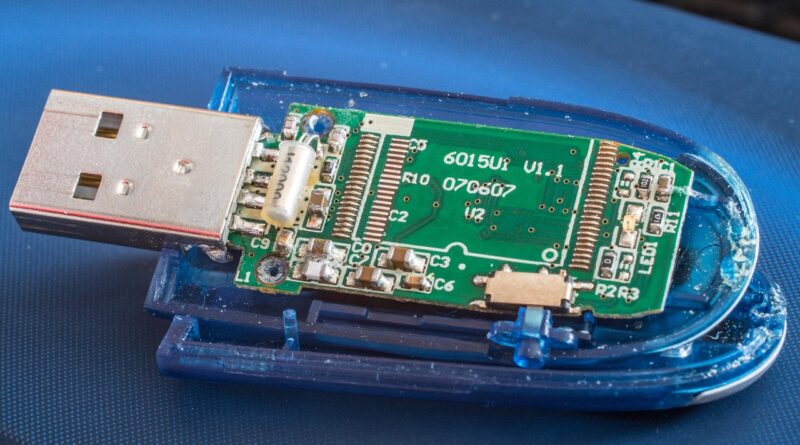
The same logic applies to more complex electronics. A smart sensor board may include a regulator, microcontroller, oscillator, memory, connectors, capacitors, resistors, protection diodes, and a communication interface. Although the number of parts increases, the basic questions remain: where does energy enter, where does current flow, what uses the energy, what controls it, and what prevents unsafe operation?
Common mistakes when learning circuit components
- Confusing voltage with current: Voltage is the electrical potential difference, while current is the flow of charge. A circuit needs the right relationship between both.
- Ignoring power ratings: A component can have the correct value but still fail if it cannot dissipate heat.
- Assuming all grounds are the same: Ground can mean signal reference, chassis connection, protective earth, or a separated return path depending on the design.
- Forgetting polarity: Batteries, diodes, LEDs, electrolytic capacitors, and many integrated circuits must be connected in the correct orientation.
- Using control parts as if ratings do not matter: Switches, relays, and transistors must match voltage, current, load type, and thermal conditions.
- Treating schematic symbols as physical layout: A schematic shows electrical relationships, not necessarily where parts sit on a board.
For anyone building or analyzing circuits, a reliable habit is to identify the role of every part before changing values or replacing components. If a part limits current, stores energy, filters noise, protects against faults, or switches a load, that role should guide the replacement choice.
Frequently asked questions
What is the most essential component in an electric circuit?
No single component is enough by itself. A useful circuit needs at least a source, a conductive path, and a load. In most practical circuits, a switch or other control element and some form of protection are also needed.
Is a resistor always required in a circuit?
No. Some circuits may not need a separate resistor, but resistance is always present in real conductors and components. A resistor is required when the design needs a controlled resistance value, such as for LED current limiting, voltage division, biasing, filtering, or timing.
What is the difference between active and passive components?
Passive components such as resistors, capacitors, and inductors shape electrical behavior without providing gain. Active components such as transistors and integrated circuits can switch signals, amplify, regulate, or process information when used with a power source. Diodes are semiconductor components commonly used to control current direction and protect circuits.
Why does a circuit need protection components?
Protection components reduce the risk of damage during overloads, short circuits, reversed connections, voltage spikes, and overheating. They do not replace careful design, but they make failures less likely to spread or become unsafe.
How should beginners start reading a circuit diagram?
Start by finding the power source and ground or return path. Then identify the load, follow the current path, locate switches or control devices, and note any resistors, capacitors, diodes, or protective parts that affect operation. Reading by function is usually easier than memorizing symbols alone.