Transistor current components explained for circuit design
Understanding transistor current components
Transistor current components are the currents that enter, leave, control, or are influenced by a transistor in a circuit. In a bipolar junction transistor, the main current components are base current, collector current, and emitter current. In a field-effect transistor, the most important practical currents are drain current, source current, gate leakage current, and transient gate-charge current.
In real hardware, these currents are also shaped by resistors, capacitors, diodes, drivers, PCB copper, and heat paths. A transistor is not only an on/off part. It is a current-handling device whose behavior depends on terminal currents, voltage stress, temperature, operating region, package limits, and the surrounding components.
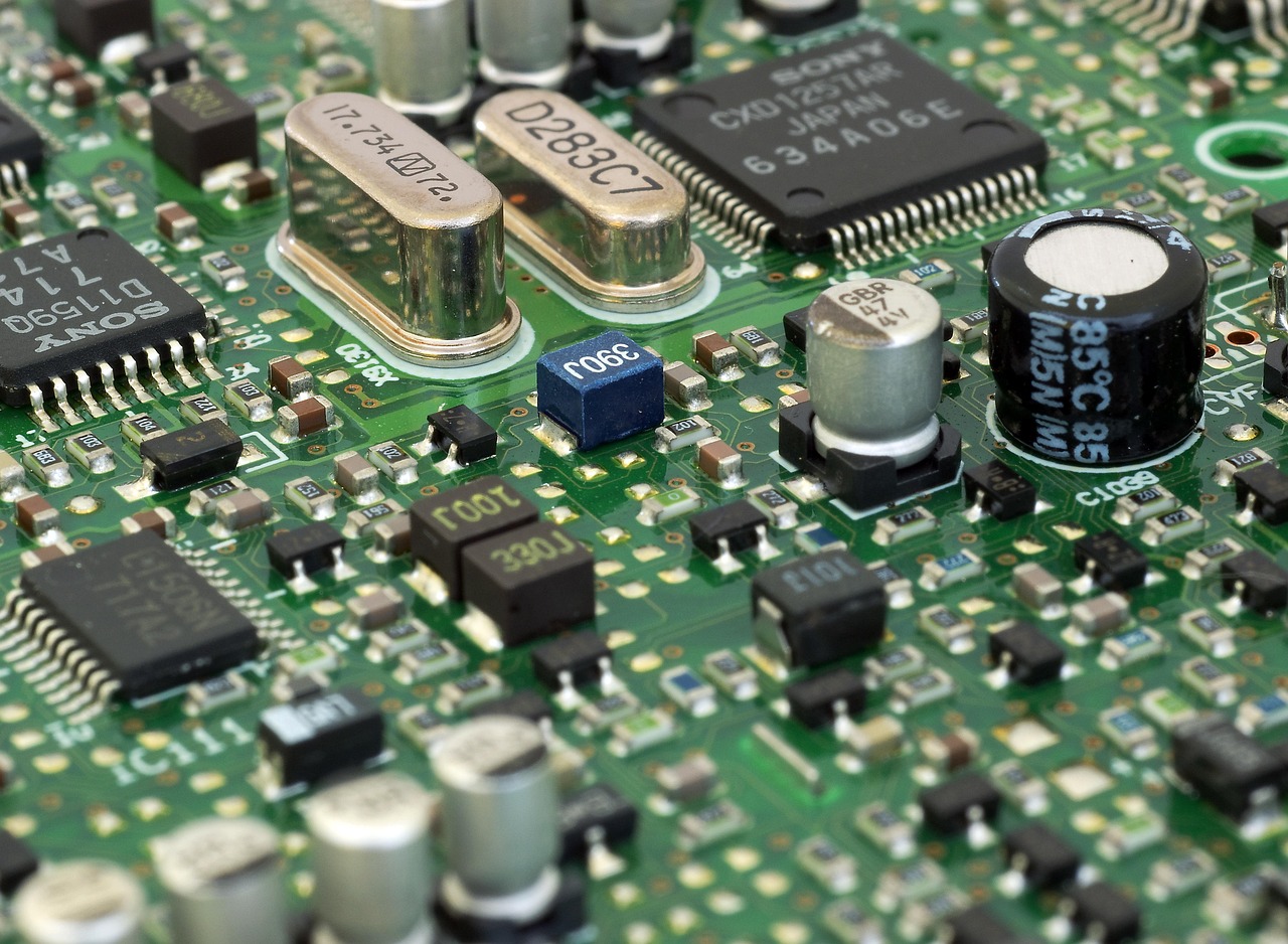
This article explains what transistor current components mean in circuit design, repair, and component selection. For more background articles on electronic parts, visit the Components section.
What does current mean in a transistor?
Current in a transistor is not a single fixed value. It changes with device type, circuit connection, load, and operating mode. A small-signal amplifier, a low-side switch, a linear regulator pass element, and a motor driver may all use transistors, but each design has different current questions.
For a BJT, current is normally described through three terminals: base, collector, and emitter. Base current is the control input, collector current is the larger controlled current through the load, and emitter current is the sum of the other two terminal currents under normal operation. In simplified DC terms:
- Emitter current equals collector current plus base current.
- Collector current is related to base current by current gain, often shown as beta or hFE.
- Current gain is not fixed; it varies with part number, collector current, voltage, temperature, and manufacturing spread.
For a MOSFET, the gate is insulated, so steady-state gate current is very small in normal operation. The gate still needs charge during switching. A MOSFET driver may draw little DC gate current, but it may need short, high-current pulses to charge and discharge the gate quickly. Drain current is the main load current, and the source terminal completes the load path.
BJT current components
A BJT is often described as a current-controlled current device. That is a useful model, but it can be misleading if the design relies only on ideal current gain. In real circuits, BJT current components must be checked against saturation behavior, power dissipation, bias stability, and safe operating conditions.
Base current
Base current is the small input current that allows a BJT to conduct a larger collector current. In switching circuits, designers usually provide more base drive than the minimum theoretical value so the transistor enters saturation reliably. In amplifier circuits, base current affects input impedance and the bias point. If the base is driven directly from a microcontroller or logic output, a base resistor is normally required to limit current and protect both the transistor and the control pin.
Collector current
Collector current is often the current designers care about most because it flows through the load. It may be LED current, relay coil current, sensor excitation current, or part of an amplifier signal. The maximum collector current shown in a datasheet is not a guarantee that the transistor can carry that current under every voltage and temperature condition. Power dissipation and thermal resistance often become the practical limits before the headline current rating is reached.
Emitter current
Emitter current is the total current leaving or entering the emitter terminal, depending on transistor polarity and circuit direction. In many NPN low-side switch circuits, emitter current is close to collector current because base current is comparatively small. In precision or analog circuits, that small difference can still matter. Emitter resistors are often used to improve bias stability, share current, or add negative feedback.
Leakage current
Leakage current is the small unwanted current that flows when a transistor is intended to be off. It usually increases with temperature. In low-power battery circuits, high-temperature equipment, sensor interfaces, or high-value resistor networks, leakage can become large enough to cause false readings or unexpected switching.
MOSFET current components
A MOSFET is commonly selected when low control power, high switching speed, or low conduction loss is required. Its current components differ from a BJT because the gate is voltage-driven and insulated. Current still remains central to MOSFET design: drain current, gate charge current, body diode current, avalanche stress, and heat all affect reliability.
Drain current
Drain current is the main load current through a MOSFET. Datasheets often list continuous drain current under specific test conditions, but that number depends heavily on case temperature, board copper area, airflow, and package capability. A MOSFET with a high current rating on paper may not be suitable on a small PCB unless there is enough copper area to remove heat.
Gate current and gate charge
In steady DC operation, the MOSFET gate draws very little current. During switching, however, the gate behaves like a capacitive load. The driver must supply and remove charge to change the gate voltage. Faster switching usually requires higher peak gate current. Slower switching can reduce driver stress and electromagnetic noise, but it may increase switching loss because the MOSFET spends more time between fully off and fully on.
Source current
Source current completes the conduction path. In low-side switching, the source is commonly tied to ground or to a current-sense resistor. In high-side switching or current-source circuits, the source voltage may move with the load, which changes the gate-to-source voltage. Designers should evaluate the voltage between gate and source, not only the gate voltage relative to system ground.
Body diode and reverse current
Most power MOSFETs include an intrinsic body diode. In motor drives, inductive loads, synchronous rectifiers, and reverse-polarity paths, current may flow through this diode during part of the switching cycle. The body diode has voltage drop, reverse recovery behavior, and thermal consequences. Treating it as an ideal free diode is a common source of design problems.
How supporting components control transistor current
Transistors rarely operate alone. The surrounding circuit determines how current starts, stops, rises, falls, and responds to faults. These supporting parts are often as important as the transistor choice itself.
| Supporting component | Current-related role | Typical design concern |
|---|---|---|
| Base resistor | Limits BJT base current | Too high may prevent saturation; too low may overload the driver |
| Gate resistor | Controls MOSFET switching speed and gate current peaks | Too high increases switching loss; too low can cause ringing or driver stress |
| Emitter or source resistor | Adds current feedback or enables current sensing | Creates voltage drop and power loss |
| Pull-up or pull-down resistor | Defines off-state control voltage | Wrong value may cause slow switching or unwanted turn-on |
| Flyback diode or clamp | Provides a safe path for inductive current | Clamp choice affects release time, voltage stress, and heat |
| Heat sink or copper area | Removes heat caused by current and voltage drop | Thermal design must match real load and ambient temperature |
These parts turn a transistor from a theoretical device into a reliable circuit element. A relay driver, for example, is not only an NPN transistor and a coil. It also needs a base resistor, a flyback path, and enough margin for coil current and temperature. A MOSFET LED driver is not only a MOSFET and a strip of LEDs. It also needs a gate network, current control, thermal margin, and awareness of wiring inductance. See also: Gadgets.
Current ratings are not the same as usable current
One of the most important lessons in transistor selection is that maximum current ratings are conditional. A datasheet may list collector current or drain current prominently, but usable current depends on several interacting limits.
- Power dissipation: current creates heat when voltage is also present across the transistor. The basic relationship is power equals voltage times current.
- On-state resistance or saturation voltage: MOSFETs dissipate conduction power mainly through on-resistance, while saturated BJTs dissipate power through collector-emitter saturation voltage.
- Temperature: higher ambient temperature reduces the safe power that a package can dissipate.
- Pulse duration: a transistor may tolerate higher pulsed current than continuous current, but only within the pulse limits described by the datasheet.
- Safe operating area: voltage and current combinations must stay within the device’s safe operating boundary, especially in linear operation.
- PCB layout: copper area, trace width, via count, and airflow influence actual temperature rise.
For switching applications, designers often focus on conduction loss and switching loss. For linear applications, the transistor may dissipate much more heat because it intentionally operates with both current and voltage across it. A part that works well as a low-resistance switch can fail quickly as a linear pass element if the safe operating area is not checked.
Design checklist for transistor current components
A practical current review should happen before the schematic is finalized and again before layout release. The following checklist helps reduce common errors.
- Identify the load current. Use worst-case load current, not only typical current.
- Choose the transistor type. Use a BJT when current gain, cost, or analog behavior fits the job; use a MOSFET when low drive current or low conduction loss is more important.
- Check control capability. Confirm that the driver can provide enough BJT base current or enough MOSFET gate drive voltage and charge current.
- Calculate heat. Estimate conduction loss, switching loss where relevant, and package temperature rise.
- Review off-state current. Leakage, pull-down values, and high-temperature behavior can matter in low-power circuits.
- Protect against inductive current. Coils, motors, relays, solenoids, and long cables need current paths or clamps when switched off.
- Check transient conditions. Startup, short circuit, hot plug, reverse polarity, and stalled motor current can exceed normal operating current.
- Validate layout. High-current loops should be short, copper should be adequate, and sense traces should not share noisy power paths.
This checklist does not replace device-specific calculations, but it keeps the design discussion focused on real current paths rather than only the symbolic transistor model.
Common mistakes when working with transistor current
The first common mistake is assuming that BJT current gain is a precise design constant. In production, hFE can vary widely, so switching circuits should be designed with forced beta or sufficient base overdrive instead of relying on a single typical gain value.
The second mistake is treating MOSFET gates as if they require no current under all conditions. DC gate current is tiny in normal operation, but switching a power MOSFET quickly can demand meaningful peak current from the driver. Weak drive can make the device heat excessively during transitions.
The third mistake is using headline current ratings without thermal analysis. A transistor may be electrically capable of carrying a current but thermally unsuitable in a small enclosure or on a compact board. Package, copper, duty cycle, ambient temperature, and airflow must be considered together.
The fourth mistake is ignoring current paths after turn-off. Inductive loads try to keep current flowing. Without a diode, snubber, TVS clamp, or other controlled path, the transistor may see damaging voltage spikes. The right protection depends on the required release speed, voltage limits, and energy involved.
The fifth mistake is measuring current in a way that changes the circuit. Long meter leads, high burden voltage, shared ground paths, and probe inductance can distort switching behavior. Current shunts, current probes, and differential measurements should be selected according to frequency, current level, and acceptable voltage drop.
Frequently asked questions
What are the main current components of a BJT?
The main BJT current components are base current, collector current, and emitter current. In normal operation, emitter current equals the sum of collector current and base current. Leakage current is also important in off-state and high-temperature designs.
What current matters most in a MOSFET?
Drain current is usually the main load current, but gate charge current matters during switching. Source current, body diode current, leakage current, and transient fault current can also determine whether the design is reliable.
Why is a transistor current rating not enough for selection?
A current rating is measured or specified under defined conditions. Real usable current also depends on voltage, power dissipation, temperature, duty cycle, board layout, package thermal resistance, and safe operating area.
Do transistors control current or voltage?
It depends on the transistor type and circuit model. A BJT is commonly controlled by base current, while a MOSFET is controlled mainly by gate-to-source voltage. In both cases, the result designers care about is the controlled current through the load.
How can current be limited in a transistor circuit?
Current can be limited with resistors, feedback networks, current-sense elements, active current-limit circuits, driver control, fuses, resettable protectors, or power management ICs. The best method depends on accuracy, efficiency, cost, fault behavior, and heat.
Key takeaway
Transistor current components are not abstract textbook details. They determine whether a circuit switches cleanly, amplifies predictably, survives faults, and stays within thermal limits. For BJTs, base, collector, and emitter currents define control and load behavior. For MOSFETs, drain current, gate charge current, source current, leakage, and body diode current are central to real performance. Good transistor design means following every current path, checking worst-case conditions, and selecting the supporting components that keep the device safe and stable in the actual circuit.