Transformers in electronics for power, isolation and signal design
Why transformers still matter in modern electronics
Transformers in electronics are far more than legacy power-supply parts. They step AC voltages up or down, provide galvanic isolation, match impedance, sense current, drive gates, couple pulses, and help control noise between circuits. In USB chargers, industrial controllers, audio equipment, network hardware, and measurement instruments, the transformer can affect efficiency, electromagnetic interference, safety spacing, temperature rise, and long-term reliability.
A transformer transfers energy through a changing magnetic field, rather than through a direct electrical connection between windings. That is why transformers are so common in isolated power supplies and signal interfaces. It is also why a conventional transformer cannot pass steady DC on its own; DC applications normally need switching circuitry to create a changing waveform first. You can also explore more in Components.
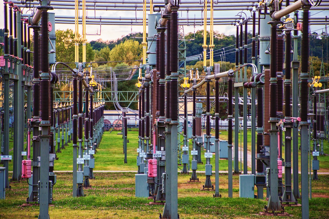
This guide focuses on electronics-level transformers rather than utility-scale grid equipment. For more component explainers and design context, visit the Components section.
How a transformer works at circuit level
A basic transformer has at least two windings on a magnetic core. The primary winding receives an alternating or pulsed voltage. The resulting changing current creates changing magnetic flux in the core, and that changing flux induces voltage in the secondary winding. In an ideal transformer, the voltage ratio is approximately proportional to the turns ratio: more secondary turns produce a higher secondary voltage, while fewer turns produce a lower secondary voltage.
Real transformers are not ideal. Copper resistance causes winding loss. Core materials create hysteresis and eddy-current loss. Some magnetic flux does not link both windings, which creates leakage inductance. The core can saturate if the volt-seconds applied to a winding exceed what the design can support. These non-ideal effects determine whether the transformer runs cool, meets regulation targets, and survives fault or overload conditions.
Frequency has a major effect on size. A 50 or 60 Hz mains transformer needs a relatively large iron or steel core because the magnetic flux changes slowly. A switch-mode power supply transformer can be much smaller because it operates at tens or hundreds of kilohertz. The smaller magnetic component comes with added design work, including the switching controller, high-frequency magnetic design, insulation evaluation, and EMI control.
Main types of transformers used in electronics
Electronics designers use several transformer families, each optimized for a different job. Selecting a transformer by voltage alone is a common error. Frequency, waveform, insulation, current, duty cycle, thermal environment, and certification context can be just as important.
| Transformer type | Typical role | Key design concern |
|---|---|---|
| Line-frequency power transformer | Steps AC mains up or down in linear power supplies | Size, heat, regulation, insulation, and mains safety |
| Switch-mode power transformer | Transfers energy in flyback, forward, half-bridge, full-bridge, or LLC converters | Core selection, saturation, leakage inductance, EMI, and isolation barrier design |
| Isolation transformer | Separates two circuits while transferring AC power or signals | Creepage, clearance, dielectric strength, and leakage current |
| Audio transformer | Couples audio signals or matches impedance | Bandwidth, distortion, shielding, and low-frequency saturation |
| Current transformer | Senses AC current without putting a resistor directly in the high-current path | Burden resistor value, accuracy, saturation, and open-secondary protection |
| Pulse or gate-drive transformer | Transfers pulses or isolated drive signals | Pulse width, reset behavior, propagation performance, and insulation rating |
| RF transformer or balun | Matches impedance or converts balanced and unbalanced signals | Frequency range, insertion loss, winding capacitance, and layout |
A common-mode choke is sometimes confused with a transformer because it also uses windings on a core. Its purpose is different. It impedes common-mode noise while allowing normal differential current to pass. It is a magnetic component, but it is not normally used to transfer useful energy from a primary winding to a secondary winding.
Power transformers in linear and switch-mode supplies
In a traditional linear supply, the transformer usually operates directly from the mains frequency. It steps the voltage down to a safer or more useful AC level, then rectifiers and capacitors produce DC. Linear supplies are simple, generate little high-frequency switching noise, and remain useful in audio, instrumentation, laboratory, and other low-noise designs. Their drawbacks are weight, volume, and heat, especially when the design must support a wide input-voltage range or significant load current.
Switch-mode supplies use a different architecture. The AC line is rectified, switched at high frequency, passed through a high-frequency transformer when isolation or voltage conversion is required, and then rectified and filtered again on the output side. This method supports compact chargers, adapters, embedded power modules, LED drivers, industrial supplies, and isolated DC-DC converters. The tradeoff is higher design complexity: switching edges create conducted and radiated emissions, transformer leakage can produce voltage spikes, and the insulation system must be suitable for both normal operation and fault conditions.
Flyback converters are common at low to moderate power because one magnetic component can store and transfer energy. Forward and bridge topologies are often chosen when power level, efficiency, or output current requirements exceed what a flyback design can handle comfortably. Resonant converters such as LLC designs can reduce switching loss and improve efficiency, but they depend strongly on transformer and resonant-tank parameters.
Isolation, safety, and standards that affect transformer selection
Isolation is one of the main reasons to use a transformer in electronics. Galvanic isolation means the primary and secondary circuits do not share a direct conductive path. This can reduce shock risk, break ground loops, protect measurement inputs, and allow one circuit domain to float relative to another. Isolation, however, is not achieved simply by placing two coils on one core. Winding construction, insulation tape, bobbin design, creepage distance, clearance distance, dielectric test level, and the certified material system all matter.
Several standards and regulatory frameworks may apply, depending on the product and market. IEC 61558-1:2017 is a key international reference for the safety of transformers, reactors, power supply units, and combinations of those products, including electrical, thermal, and mechanical safety aspects. IEC/UL 62368-1 is often relevant for audio, video, information, and communication technology equipment, and national editions or adoption dates should be checked for the intended market. In the United States, OSHA recognizes Nationally Recognized Testing Laboratories for product safety testing, and recognized standards can include equipment safety standards used around power supplies and electronic products.
It is also important not to confuse electronics transformers with distribution transformers used in the electric grid. The U.S. Department of Energy finalized amended energy conservation standards for distribution transformers in 2024, with compliance required on and after April 23, 2029. Those rules are directed at defined distribution transformer categories, not most small PCB transformers or signal transformers. Designers should still verify whether a product falls under energy efficiency, safety, or external power supply rules in its target market.
Electrical parameters that matter before buying or designing one
The first parameter many engineers check is turns ratio, but it is only the starting point. For a power transformer, the required output voltage has to be considered under line tolerance, load variation, rectifier drop, ripple, regulation, temperature, and aging. A transformer that appears correct at no load may sag too much at full load, or it may overheat because the RMS current is higher than expected.
Power rating also depends heavily on operating conditions. A transformer rated for a sine-wave mains application cannot automatically be used in a pulsed converter. Current waveform shape affects RMS heating. Duty cycle affects flux reset. Ambient temperature and enclosure airflow affect allowable temperature rise. If the transformer is installed inside a sealed plastic product, a rating measured in open air may not represent the final product condition.
For switching converters, magnetizing inductance, leakage inductance, interwinding capacitance, core material, saturation current, and winding resistance become critical. High leakage inductance can increase spikes and switching loss, although some leakage may be intentionally used in resonant designs. Low interwinding capacitance can reduce common-mode noise across an isolation barrier, but construction choices that reduce capacitance may increase size or cost. See also: Gadgets.
For signal transformers, bandwidth, insertion loss, phase shift, balance, distortion, and impedance matching are often more important than power rating. An audio transformer must handle low frequencies without saturating and high frequencies without excessive roll-off. An Ethernet magnetics module must meet the electrical and isolation needs of the interface it supports. A current transformer must be paired with the correct burden and must not be operated with an unsafe open secondary in installations where high secondary voltage could develop.
Practical selection checklist for electronics projects
A good transformer selection process starts with the circuit function, not the catalog page. Define whether the part is transferring power, coupling a signal, providing isolation, sensing current, matching impedance, or suppressing noise. Then review the electrical, mechanical, safety, and thermal constraints together.
- Confirm the waveform and frequency. A 60 Hz transformer, a 100 kHz flyback transformer, and an RF transformer are not interchangeable.
- Verify voltage and current under worst case. Include input tolerance, load transients, startup, short-circuit behavior, and maximum ambient temperature.
- Check saturation margin. Core saturation can cause high current, overheating, distortion, converter failure, or protective shutdown.
- Review insulation requirements. For mains-connected or hazardous-voltage circuits, check the required working voltage, dielectric withstand level, creepage, clearance, and insulation class.
- Evaluate thermal rise. Temperature depends on copper loss, core loss, mounting, enclosure airflow, and nearby heat sources.
- Consider EMI early. Winding layout, shielding, leakage inductance, snubbers, Y capacitors, and PCB return paths all influence emissions.
- Use approved parts where certification matters. A certified transformer or power module can simplify product evaluation, but it does not remove the need to test the complete product.
For prototypes, off-the-shelf transformers are often the lower-risk path because their ratings and construction are already documented. Custom transformers make sense when power density, cost at volume, unusual voltage ratios, mechanical fit, leakage targets, or isolation requirements cannot be met with standard parts.
Common design mistakes and how to avoid them
One common mistake is applying DC to a transformer winding as if it were a resistor. A conventional transformer needs changing flux. Without proper switching, reset, or current limiting, DC can drive the core into saturation and overheat the winding. Another mistake is ignoring inrush current. Line-frequency transformers and bulk capacitors can draw large startup currents, so fuses, thermistors, relays, or active inrush limiting may be needed.
In switch-mode designs, leakage inductance and parasitic capacitance are often underestimated. Leakage energy can create voltage spikes on switching devices, while interwinding capacitance can inject common-mode noise from primary to secondary. Snubber networks, clamp circuits, shielding, and careful layout are not optional details in many isolated supplies.
Safety spacing errors are especially serious. A transformer footprint may appear to separate primary and secondary pins, but the PCB layout, slots, contamination environment, altitude, coating, connector placement, and enclosure design can change the actual creepage and clearance situation. Product safety is evaluated at system level, not just component level.
Finally, avoid treating standards as generic labels. A transformer marked for one application may not be suitable for medical, industrial control, household appliance, measurement, or AV/ICT equipment without further evaluation. The correct standard depends on product category, market, environment, user access, voltage, and energy level.
Frequently asked questions
Do transformers work with DC?
A conventional transformer does not transfer steady DC because it depends on changing magnetic flux. DC-DC converters use switches to turn DC into a pulsed or alternating waveform, allowing a high-frequency transformer to transfer energy and provide isolation.
Why are switch-mode transformers smaller than 60 Hz transformers?
Higher frequency allows the transformer to transfer energy with a smaller core and fewer turns for the same general power range. The result is compact size, but the design must manage switching loss, EMI, insulation, and thermal behavior.
Is an isolation transformer always safer?
Isolation can reduce certain shock and ground-loop risks, but it is not a complete safety solution by itself. The insulation system, spacing, leakage current, enclosure, protective devices, grounding approach, and applicable product standard all affect real safety.
Can one transformer be used for both power and signal coupling?
Usually no. Power transformers are optimized for energy transfer and thermal performance, while signal transformers are optimized for bandwidth, impedance, distortion, and waveform fidelity. Some pulse transformers transfer signal energy, but their ratings must match the actual pulse conditions.
What is the most important transformer specification?
There is no single universal specification. For a mains power transformer, insulation and thermal rating may dominate. For a flyback transformer, magnetizing inductance, saturation margin, leakage, and isolation are critical. For a signal transformer, bandwidth and impedance behavior may matter most.
Bottom line
Transformers remain essential components in electronics because they solve several design problems at once: voltage conversion, isolation, signal coupling, impedance matching, and current sensing. The right choice depends on the waveform, frequency, power level, insulation requirement, thermal environment, EMI target, and applicable safety framework. Treat the transformer as part of the complete circuit and product safety design, not as an isolated catalog item, and the result will be more reliable, easier to certify, and easier to manufacture.