Circuit board components explained for design, assembly and repair
Circuit board components are the electronic, electromechanical and protective parts mounted on a printed circuit board to make an electronic product work. Resistors set current and voltage levels, capacitors store and filter energy, integrated circuits process information, connectors link the board to other systems and protective parts help the assembly tolerate faults. Understanding these parts matters in PCB design, troubleshooting, sourcing and quality inspection because a board is not evaluated by its schematic alone. It also has to withstand heat, vibration, soldering, handling and its intended operating environment. This guide explains the main component groups, how they appear on a PCB, why package choice matters and what standards-based inspection usually considers.
For more background on related electronic parts, see the Components section.
What counts as a circuit board component?
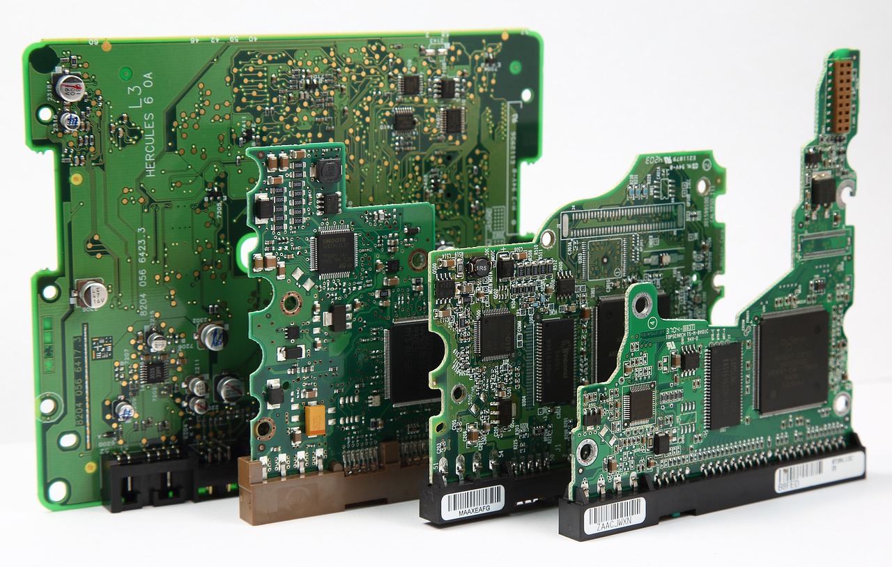
A circuit board component is any part intentionally attached to a PCB to perform an electrical, mechanical, thermal or protection function. In everyday use, the term usually refers to visible mounted parts such as resistors, capacitors, diodes, chips, connectors, switches, relays, fuses, crystals, inductors and sensors. It can also include less obvious items such as test points, jumpers, heat sinks, shielding cans and board-level protection devices.
It is useful to separate the bare board from the assembly. The bare PCB provides copper traces, insulating laminate, solder mask, pads, vias and mechanical form. Once components are soldered or otherwise mounted, the result is commonly called a printed circuit board assembly, PCB assembly or PCBA. This distinction matters because bare board quality and assembled board quality are evaluated with different documents and inspection criteria. IPC documents such as IPC-6012 focus on rigid printed board qualification and performance, while assembly documents such as IPC J-STD-001 and IPC-A-610 are used for soldering requirements and acceptability of electronic assemblies.
Components can be grouped by function, mounting style or package. A resistor and a microcontroller have very different jobs, but both may be surface-mounted. A connector and a transformer may both be through-hole parts, but one mainly provides interconnection while the other transfers energy. Good PCB work requires all three views at the same time.
Main types of circuit board components and what they do
Most boards contain a mix of passive, active, electromechanical, protection and interconnection components. The exact mix depends on whether the product is a power supply, sensor module, radio device, industrial controller, medical instrument or consumer product.
Passive components
Passive components do not amplify signals or make logical decisions, but they are essential for stable circuits. Resistors limit current, divide voltage, set bias points and terminate signal lines. Capacitors store charge, smooth power rails, couple AC signals and reduce noise. Inductors store energy in a magnetic field and are common in filters, DC-DC converters and radio-frequency circuits.
Passive parts can look simple, but their real behavior depends on tolerance, temperature coefficient, voltage rating, equivalent series resistance, equivalent series inductance and package size. A capacitor with the right nominal value, for example, may still be unsuitable if its voltage derating, dielectric behavior or ripple-current capability is inadequate for the application.
Active components
Active components control current flow, switch signals, amplify voltages or perform computation. Diodes conduct mainly in one direction and are used for rectification, clamping and protection. Transistors act as switches or amplifiers. Integrated circuits combine many devices into one package and may perform power conversion, memory, sensing, communication, timing or microprocessor functions.
Integrated circuits are often the most information-dense components on a board. A small IC may require correct power sequencing, decoupling capacitors, clock sources, reset circuitry, thermal paths, firmware support and controlled signal routing. For that reason, a board can fail even when the IC itself is genuine and electrically intact. Layout, grounding, soldering and surrounding components all affect the result.
Electromechanical and interface components
Electromechanical components connect the PCB to users, cables, enclosures and moving systems. Examples include connectors, switches, relays, sockets, terminal blocks, buttons and board-mounted displays. These parts often experience mechanical stress that small chip components do not. Cable pull, repeated mating cycles, vibration and enclosure misalignment can damage solder joints or pads if the design does not provide adequate support.
Connectors deserve special attention because they create many real-world failure points. Connector selection should consider pitch, current rating, voltage spacing, locking method, plating, insertion cycles, strain relief and compatibility with the cable assembly. In repair work, connector damage is often easier to see than a failing semiconductor, but the root cause may still be mechanical design rather than user handling alone.
Protection, timing and thermal components
Many boards include components whose main role is to protect or stabilize the system. Fuses, resettable polymer fuses, transient voltage suppressor diodes, metal oxide varistors, common-mode chokes and electrostatic discharge protection arrays can prevent a fault from spreading. Crystals, ceramic resonators and oscillators provide timing references for microcontrollers, radios and communication interfaces. Heat sinks, thermal pads and metal-core substrates move heat away from power devices.
These parts may not define the product’s visible features, but they strongly influence reliability. A missing or poorly selected protection part may not affect a prototype on the bench, yet it can cause field failures when the product is exposed to electrostatic discharge, surge, overload or thermal stress.
How to identify components on a PCB
Technicians usually identify circuit board components through a combination of reference designators, package shape, markings, schematic context and measurement. The most reliable method is to use the assembly drawing, bill of materials and schematic together. When those documents are unavailable, visual identification becomes more important, but also less certain.
Reference designators are short labels printed on the silkscreen or listed in design files. Common examples include R for resistor, C for capacitor, L for inductor, D for diode, Q for transistor, U or IC for integrated circuit, J or P for connector, F for fuse, Y or X for crystal, SW for switch and TP for test point. These labels are not universal rules, but they are widely used conventions.
| Designator | Common component | Typical role |
|---|---|---|
| R | Resistor | Current limiting, pull-up, pull-down, voltage division |
| C | Capacitor | Filtering, decoupling, timing, energy storage |
| L | Inductor | Filtering, energy storage, impedance control |
| D | Diode or LED | Rectification, indication, clamping, reverse protection |
| Q | Transistor or MOSFET | Switching, amplification, power control |
| U | Integrated circuit | Processing, regulation, memory, communication |
| J or P | Connector | Board-to-board, wire-to-board or external interface |
| F | Fuse | Overcurrent protection |
| Y or X | Crystal or resonator | Clock and timing reference |
Package style gives another clue. Tiny rectangular two-terminal parts are often resistors or capacitors. Molded three-terminal packages may be transistors, regulators or sensors. Large multi-pin packages are usually ICs. Metal cans may be crystals, oscillators or shielding features. However, visual assumptions can be wrong because different components can share similar packages. A two-terminal black chip may be a resistor, diode, thermistor or ferrite bead depending on its marking and circuit position.
Component markings are useful but limited. Larger ICs often have manufacturer codes and part numbers. Small passive components may use three- or four-digit codes, while many small capacitors have no visible value marking at all. Rework and inspection should therefore avoid relying on appearance alone when safety, high current or precise performance is involved.
Surface mount and through-hole components
Most modern circuit boards use surface mount technology because it supports small packages, automated placement, high component density and efficient reflow soldering. Surface mount components sit on pads on the board surface rather than passing leads through drilled holes. Common examples include chip resistors, multilayer ceramic capacitors, small-outline ICs, quad flat packages, ball grid arrays and many modern connectors. See also: Gadgets.
Through-hole components have leads that pass through plated holes and are soldered on the opposite side or in a wave/selective soldering process. They remain important when a part needs mechanical strength, high current capacity, a user-serviceable connection or compatibility with legacy manufacturing. Large electrolytic capacitors, power connectors, transformers, relays and terminal blocks often use through-hole mounting, although surface mount versions also exist.
The choice is not only about size. Surface mount parts can reduce parasitic inductance and support high-speed layouts, but they may be harder to hand-repair. Through-hole parts can provide strong anchoring, but they consume board area and add drilling complexity. Mixed-technology boards use both approaches when electrical and mechanical requirements justify the trade-off.
Assembly standards become important at this point. IPC announced the J revisions of IPC J-STD-001 and IPC-A-610 on April 8, 2024, describing J-STD-001 as a soldering process and material requirements document and A-610 as an acceptability standard for completed electronic assemblies. In practical terms, these documents help define what acceptable solder joints, component placement and assembly conditions look like for different product expectations.
Electrical ratings that matter when selecting components
Component selection should begin with the circuit function, but it cannot stop at nominal value. A resistor is not fully specified by ohms, and a capacitor is not fully specified by farads. Ratings, tolerances and environmental behavior determine whether the component will work reliably on the actual board.
- Voltage rating: The maximum voltage a component can safely withstand under specified conditions. Designers often derate voltage to improve reliability, especially for capacitors and semiconductors.
- Current rating: The current a device, connector, trace or protection component can carry without overheating or exceeding limits.
- Power rating: The heat a component can dissipate. A resistor operating near its rating may run hot and affect nearby parts.
- Tolerance: The permitted variation from nominal value. Precision sensing, timing and analog circuits may require tighter tolerance parts.
- Temperature range: The operating and storage limits for the component. Automotive, industrial and outdoor equipment often need wider ranges than indoor consumer products.
- Package and footprint: The mechanical and soldering interface. A correct electrical part can still be wrong if the land pattern, height or thermal pad is incompatible.
- Availability and lifecycle: Obsolete or single-source components can create production risk even if prototypes work well.
Power and thermal behavior deserve special care. A MOSFET, regulator, diode or resistor may meet its data sheet headline rating only under specific board copper area, airflow or case temperature conditions. PCB copper is part of the thermal system, not just a conductor. When the layout does not provide the expected heat-spreading path, a component can exceed safe temperature even when the schematic calculation appears correct.
Reliability, inspection and compliance considerations
Reliability comes from component choice, PCB layout, assembly control and operating environment. Common assembly-related issues include insufficient solder, solder bridging, tombstoned chip parts, lifted leads, cracked ceramic capacitors, overheated pads, reversed polarity, poor wetting, flux residue and mechanical stress around connectors. Some issues are visible under magnification, while others require electrical testing, X-ray inspection or environmental stress testing.
IPC-A-610 is widely used for finished assembly acceptability, while IPC J-STD-001 focuses on soldered electrical and electronic assembly requirements. IPC materials also describe class-based expectations, commonly understood as different levels for general electronic products, dedicated-service products and high-performance or harsh-environment products. The correct class should be agreed by contract, product risk and end-use requirements rather than chosen casually after boards are built.
Safety and regulatory requirements may also shape component decisions. UL 796 is a recognized standard for printed wiring boards, especially where flammability, construction and safety evaluation are relevant. The European Union RoHS framework restricts certain hazardous substances in electrical and electronic equipment to protect public health and the environment. These requirements do not tell an engineer which resistor value to use, but they affect material declarations, solder alloys, component finishes and supplier documentation.
Counterfeit and poorly documented components are another risk. Warning signs may include inconsistent markings, suspicious packaging, missing traceability, unusual electrical behavior or poor solderability. For high-reliability products, incoming inspection, approved vendor lists, lot traceability and controlled substitutions are not paperwork exercises; they help prevent unknown materials and uncontrolled process variation from entering the assembly.
Practical checklist for reading or reviewing a populated board
When reviewing circuit board components, a structured approach is better than scanning the board randomly. The goal is to understand function, spot obvious risks and identify which questions need documentation.
- Start with power input: Identify connectors, fuses, polarity protection, regulators and bulk capacitors. Many board failures begin at the power path.
- Follow major functional blocks: Separate power conversion, processing, communication, sensing, actuation and user-interface areas.
- Check polarity-sensitive parts: Electrolytic capacitors, diodes, LEDs, ICs and some connectors must be oriented correctly.
- Look for thermal stress: Discolored boards, browned solder mask, cracked joints and hot power devices may indicate insufficient heat management.
- Inspect mechanical interfaces: Connectors, switches and heavy components should not rely on weak solder joints alone when they experience force.
- Compare with documentation: The schematic, bill of materials and assembly drawing should match the populated board, revision and intended product configuration.
- Record uncertain findings: Unknown components should be measured or verified instead of guessed, especially in mains-powered or safety-related circuits.
This checklist is useful for repair, reverse engineering, supplier review and design-for-manufacturing discussions. It does not replace formal qualification testing, but it helps reveal mismatches between design intent and the physical assembly.
Frequently asked questions
What are the most common circuit board components?
The most common circuit board components are resistors, capacitors, diodes, transistors, integrated circuits, connectors, inductors, switches, fuses and crystals or oscillators. Their presence and quantity depend on the product type. A power supply may contain many inductors, capacitors and power semiconductors, while a digital controller may contain more ICs, connectors and timing components.
How can I tell whether a component is damaged?
Visible signs include burning, cracking, bulging, corrosion, broken leads, lifted pads, missing parts and discolored solder mask. Electrical signs include short circuits, open circuits, unstable voltage rails or abnormal heating. However, many failed semiconductors show no obvious visual damage, so measurement and circuit understanding are often required.
Why do some small PCB components have no markings?
Very small surface mount capacitors and some passive parts often have no printed value because there is not enough space, the marking process may be impractical or the manufacturer relies on reel labeling. In those cases, the bill of materials, assembly drawing or circuit measurement is needed to identify the part correctly.
Are surface mount components less reliable than through-hole components?
Not automatically. Surface mount components can be highly reliable when the footprint, soldering process and mechanical design are correct. Through-hole components may provide stronger mechanical anchoring for connectors and heavy parts, but they are not always electrically or thermally superior. Reliability depends on the application, package, board layout, assembly process and stress environment.
What standards are most often associated with PCB components and assembly?
Commonly referenced documents include IPC J-STD-001 for soldered electrical and electronic assembly requirements, IPC-A-610 for acceptability of electronic assemblies, IPC-6012 for rigid printed board qualification and performance, and UL 796 for printed wiring boards. Regulatory frameworks such as RoHS may also affect material selection and documentation for electrical and electronic equipment.