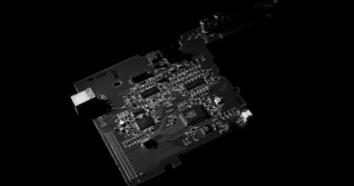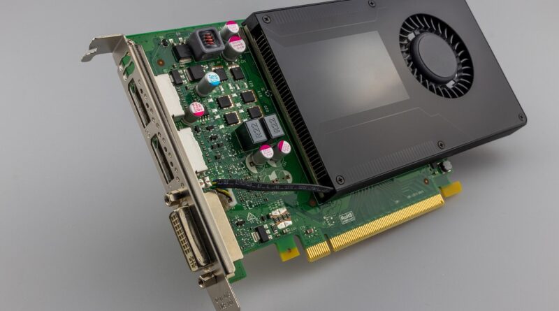
Power electronics components explained for efficient power conversion
What power electronics components do in a converter
Power electronics components are the devices and supporting parts that convert electrical energy from one form to another: AC to DC, DC to AC, one DC voltage to another, or one AC frequency and voltage to another. In an actual converter, the semiconductor switch often gets the most attention, but efficiency and reliability depend on the full stack around it: gate drivers, controllers, magnetics, capacitors, sensors, protection devices, interconnects, isolation, cooling, and packaging. The practical question is not simply which switch is fastest. It is which component set can meet voltage, current, thermal, electromagnetic interference, safety, qualification, and cost targets at the same time.
That question becomes more important as electrification expands. The International Energy Agency’s Electricity 2026 report describes electricity demand rising rapidly from 2026 to 2030, supported by electric vehicles, buildings, data centers, advanced manufacturing, and broader electrification. More electric loads mean more conversion stages, and each stage depends on well-chosen components. Related background articles are available in the Components section.
The core component stack in a power converter
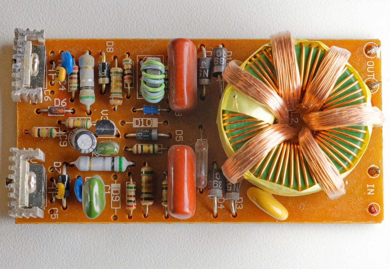
A power converter is better viewed as a coordinated component system than as a single power device. The main switch may define the headline voltage and current rating, but the surrounding components determine how close the design can get to its expected performance in service.
Power semiconductors
Power semiconductors include diodes, thyristors, MOSFETs, IGBTs, silicon carbide MOSFETs and Schottky diodes, and gallium nitride HEMTs. Their role is to block voltage when off and conduct current when on, usually at high switching speed. Key parameters include breakdown voltage, continuous and pulsed current, on-resistance or saturation voltage, switching energy, reverse recovery behavior, gate charge, thermal resistance, package inductance, and safe operating area.
Gate drivers and control ICs
Gate drivers translate low-voltage logic into the voltage and current needed to switch a power device predictably. They may include isolation, Miller clamp functions, desaturation detection, under-voltage lockout, soft turn-off, and fault reporting. Control ICs or digital controllers regulate the converter through pulse-width modulation, frequency control, current-mode control, power factor correction, synchronous rectification, or motor-control algorithms.
Magnetics and capacitors
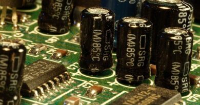
Inductors, transformers, DC-link capacitors, snubbers, and output capacitors store and transfer energy. They also filter ripple, shape transient response, and affect electromagnetic interference. Higher switching frequency can often reduce the size of magnetic components, but it also raises demands on core loss, copper loss, insulation stress, proximity effect, and thermal rise. Capacitors need to be checked for voltage derating, ripple current, equivalent series resistance, lifetime at temperature, and failure mode.
Protection, sensing, and isolation
Fuses, transient voltage suppressors, varistors, current sensors, temperature sensors, isolated amplifiers, optocouplers, digital isolators, and relays protect the converter and the load. In high-power systems, protection timing is a design constraint, not an accessory. A short-circuit event can destroy a device faster than a slow controller can react, so local driver protection and layout-aware sensing often matter as much as the control code.
| Component group | Main role | Selection factors |
|---|---|---|
| Power switch | Controls energy flow | Voltage, current, losses, switching speed, package, safe operating area |
| Diode or synchronous rectifier | Provides current path during switching intervals | Reverse recovery, forward drop, timing, thermal behavior |
| Gate driver | Turns the switch on and off safely | Drive voltage, peak current, isolation, protection, propagation delay |
| Magnetics | Stores, transfers, or filters energy | Inductance, saturation current, core loss, winding loss, insulation |
| Capacitors | Stabilize voltage and handle ripple | Capacitance, ESR, ripple current, voltage derating, lifetime |
| Thermal path | Moves heat away from loss sources | Thermal resistance, interface material, airflow or liquid cooling, mounting pressure |
Silicon, SiC, and GaN are not interchangeable choices
Silicon remains widely used because it is mature, cost-effective, and available across a broad range of packages and ratings. Silicon MOSFETs are common in low-voltage and many medium-voltage converters, while IGBTs remain important in higher-power applications where conduction and switching losses are acceptable for the operating frequency. Silicon is often the right answer when supply risk, design familiarity, and cost are the main constraints.
Silicon carbide and gallium nitride are wide-bandgap semiconductor technologies. U.S. Department of Energy and NREL materials describe wide-bandgap devices as enabling higher efficiency, higher temperature operation, higher frequency, and potentially smaller systems compared with conventional silicon devices in suitable applications. That does not mean they automatically improve every converter. Their value depends on the voltage range, switching topology, driver design, layout parasitics, thermal design, and whether the system can benefit from smaller magnetics or reduced cooling.
SiC is especially relevant where voltage and temperature stress are high, such as electric vehicle traction inverters, fast chargers, photovoltaic inverters, industrial drives, and grid-connected converters. GaN is attractive in compact, high-frequency designs such as adapters, server power supplies, telecom power, point-of-load stages, and other applications where fast switching and low capacitance can improve power density. In many systems, the comparison is not simply SiC versus GaN; it is silicon versus SiC versus GaN within a specific voltage, frequency, thermal, reliability, and cost envelope.
Efficiency is a system result, not a component label
Converter efficiency comes from the combined effect of conduction loss, switching loss, magnetic loss, capacitor loss, gate-drive loss, control overhead, leakage, and cooling power. A lower on-resistance switch can still underperform if its output capacitance increases switching loss or if package inductance creates voltage overshoot. A faster device can create more electromagnetic interference if the PCB loop area, gate resistance, and return path are not controlled. A smaller inductor can reduce size but run hotter if the core material is not suitable for the ripple frequency.
This is why datasheet comparison needs context. A power MOSFET with very low on-resistance at 25°C may look attractive, but the on-resistance at high junction temperature is usually more relevant. A capacitor with adequate capacitance at room temperature may lose effective capacitance under DC bias. A gate driver with high peak current may not improve performance if layout inductance causes ringing. A thermal interface material with good conductivity may still miss the design target if mounting pressure is uneven.
A useful engineering approach is to map each loss mechanism to the component that controls it. Conduction loss points to device resistance, current waveform, connector resistance, winding loss, and copper plane design. Switching loss points to device capacitances, diode recovery, gate-drive strength, snubber design, and dead time. Thermal stress points to package resistance, heat spreading, airflow, ambient temperature, and duty cycle. Electromagnetic noise points to loop inductance, shielding, filtering, common-mode capacitance, and grounding strategy.
Packaging and thermal design decide reliability
Power electronics reliability is often limited by temperature cycling, solder fatigue, bond wire lift-off, insulation stress, moisture sensitivity, vibration, and contamination. As power density rises, packaging becomes part of the electrical design. Low-inductance packages help reduce overshoot and ringing. Kelvin-source connections improve gate control in fast-switching MOSFET and SiC designs. Power modules can reduce assembly complexity, but they require careful attention to baseplate flatness, thermal interface material, isolation rating, and mounting torque.
Thermal design should start before the PCB is finalized. The designer needs realistic loss estimates, maximum ambient temperature, airflow assumptions, heatsink or cold-plate limits, and allowable junction temperature. It is risky to rely on a single typical thermal resistance value. Real systems have hot spots, uneven copper spreading, enclosure constraints, dust accumulation, fan aging, and duty-cycle changes. For automotive, industrial, and energy applications, thermal margin is also reliability margin. See also: Gadgets.
Wide-bandgap devices make packaging and layout even more important. Their faster edges can expose parasitic inductance and capacitance that were less visible in slower silicon designs. A SiC or GaN part may be capable of high-frequency operation, but the board, driver, measurement method, and thermal path must support that speed. Otherwise, the design may need to slow the edge rate, add snubbing, or accept lower practical efficiency than expected.
Applications shape the component priorities
Different end markets put different demands on power electronics components. In an electric vehicle traction inverter, efficiency affects driving range and cooling load, but qualification, short-circuit ruggedness, vibration tolerance, and long operating life are also critical. In an onboard charger or DC fast charger, isolation, power factor correction, thermal density, connector safety, and grid interaction become central. In a photovoltaic inverter, long outdoor life, surge protection, insulation coordination, and serviceability matter as much as peak conversion efficiency.
Industrial motor drives bring another set of tradeoffs. Adjustable-speed drives must handle motor cable effects, electromagnetic compatibility, braking energy, overload behavior, and safety requirements. IEC 61800 is the major standards family associated with adjustable speed electrical power drive systems, while IEC 62477-1:2022 addresses safety requirements for power electronic converter systems and equipment up to defined low-voltage system limits. These standards do not choose the component for the designer, but they influence insulation, protection, thermal, and documentation decisions.
Data centers and telecom power systems put pressure on density, efficiency at different load levels, serviceability, and power architecture. GaN and advanced silicon devices may appear in front-end power factor correction and high-frequency DC-DC stages, but the final choice depends on cost, field reliability, manufacturability, and the ability to meet electromagnetic interference limits. Consumer chargers emphasize compactness and cost, while aerospace and medical systems emphasize qualification, traceability, derating, and failure-mode control.
Standards and qualification checks reduce hidden risk
Component selection should include standards and qualification evidence early, not after the schematic is finished. For automotive discrete semiconductors, AEC-Q101 is commonly used as a stress-test qualification framework. It does not remove the need for application validation; the AEC document itself places responsibility on users to confirm that qualification data supports the intended use. For capacitors, magnetics, connectors, insulation systems, and thermal materials, relevant standards and customer requirements vary by market.
For GaN devices, JEDEC JEP173:2019 is important because it addresses dynamic on-resistance testing for GaN HEMT-based power conversion devices. Dynamic on-resistance matters because trapping effects can make the apparent on-state resistance depend on operating and measurement conditions. This is a clear example of why wide-bandgap devices require test methods that match real switching behavior, not only static datasheet values.
A practical sourcing review should ask whether the supplier provides lifetime models, thermal impedance curves, application notes, failure-mode information, package assembly guidance, and change-notification practices. For high-reliability designs, second sourcing is more difficult with highly optimized modules or specialized GaN and SiC packages, so supply continuity should be considered alongside electrical performance.
A practical checklist for choosing power electronics components
- Define the electrical envelope. Confirm nominal and maximum voltage, transient voltage, RMS and peak current, overload duration, switching frequency, and isolation needs.
- Estimate losses before choosing packages. Compare conduction, switching, magnetic, and capacitor losses across realistic temperature and load profiles.
- Check thermal margin. Use worst-case ambient temperature, cooling degradation, interface resistance, and component aging assumptions.
- Review layout sensitivity. Fast devices require short power loops, controlled gate loops, Kelvin connections where available, and careful measurement points.
- Match qualification to the market. Automotive, industrial, medical, grid, and consumer products have different expectations for standards, documentation, and derating.
- Validate protection timing. Short-circuit, overvoltage, reverse polarity, overtemperature, inrush, and fault recovery behavior should be tested at system level.
- Consider manufacturability. Availability, package handling, soldering profile, inspection access, and field replacement can change the real cost of a component choice.
The strongest designs treat power electronics components as an interconnected system. A more advanced semiconductor can create real benefits, but only when the driver, magnetics, capacitors, PCB, thermal path, protection scheme, and standards strategy are designed around it. In that sense, component selection is not just a purchasing step; it is a core architecture decision behind efficient power conversion.
Frequently asked questions
What are the main power electronics components?
The main groups are power semiconductors, gate drivers, control ICs, magnetics, capacitors, sensors, protection devices, isolation components, connectors, PCB interconnects, and thermal management parts. In high-power systems, packaging and cooling should be treated as core components rather than mechanical afterthoughts.
Are SiC and GaN always better than silicon?
No. SiC and GaN can improve efficiency, frequency, and power density in suitable designs, but silicon remains strong in many cost-sensitive, mature, or lower-stress applications. The best choice depends on voltage, current, frequency, temperature, reliability targets, supply chain, and total system cost.
Why do passive components matter so much in power electronics?
Passives shape ripple, transient response, noise, thermal rise, and physical size. A converter with an excellent semiconductor switch can still miss efficiency, EMI, or lifetime targets if the inductor saturates, the capacitor overheats, or the transformer insulation system is not appropriate.
What should be checked first in a power component datasheet?
Start with absolute maximum ratings, recommended operating conditions, thermal resistance, loss-related parameters, safe operating area, package details, derating curves, and reliability information. Typical values are useful for comparison, but worst-case and temperature-dependent values are more important for design margin.