Switched power supply explained for electronic design and component selection
What a switched power supply does
A switched power supply, also known as a switched-mode power supply or SMPS, converts an input voltage into a regulated output by rapidly turning semiconductor switches on and off. Instead of dissipating excess voltage mainly as heat, it stores and transfers energy through inductors, transformers and capacitors. In practice, this allows high efficiency, compact construction and flexible voltage conversion.
For component selection, the rated wattage is only one part of the decision. Engineers also need to check input range, output accuracy, ripple, efficiency at realistic load points, thermal margin, isolation, safety approvals, electromagnetic interference and protection features.
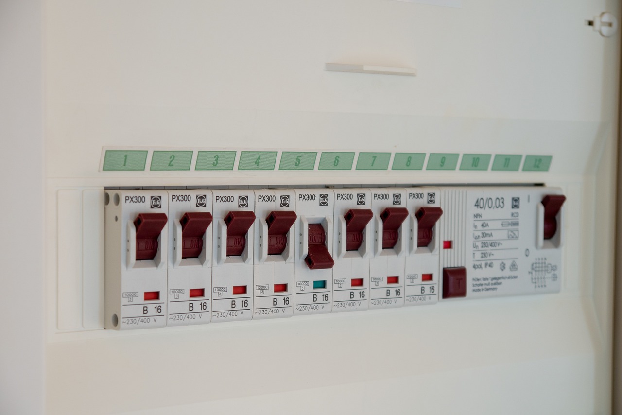
Switched power supplies are used across phone chargers, industrial controllers, LED drivers, network equipment, appliances, medical instruments, computer power units and embedded systems. The same basic conversion principle can step voltage down, step it up, invert polarity or provide isolated outputs, depending on the topology.
For readers comparing related power components, the Components section offers additional context on parts and design choices used around power conversion circuits.
How a switched power supply works
The core of a switched power supply is a controlled power switch, usually a MOSFET or another semiconductor device. A controller drives the switch at a fixed or variable frequency. During one part of the cycle, energy is stored in a magnetic component such as an inductor or transformer. During another part, that energy is released to the output. A feedback loop senses the output voltage or current and adjusts the duty cycle, frequency or pulse pattern to keep the output within specification.
Many designs use pulse-width modulation. If the output voltage drops under load, the controller can increase the effective on-time of the switch. If the output rises, the controller reduces energy transfer. More advanced controllers may use current-mode control, quasi-resonant switching, synchronous rectification or digital supervision, but the purpose is still the same: regulate output power with lower losses than a linear pass element.
High switching frequency is also why switched supplies can be much smaller than older mains-frequency transformer supplies. A transformer operating at tens or hundreds of kilohertz can often be smaller than a 50 Hz or 60 Hz transformer for the same power level. The tradeoff is that fast high-frequency current edges create noise that must be managed through layout, filtering, shielding and compliance testing.
Switched power supply vs linear power supply
A linear power supply regulates by keeping a transistor or regulator element in its linear operating region. It is simple, predictable and often valued for low output noise. Its main limitation is efficiency. If a linear regulator drops a large voltage at meaningful current, the difference is converted into heat. That heat raises enclosure temperature, reduces available current and may require large heat sinks.
A switched power supply operates differently. The power device is ideally either fully on, where voltage drop is low, or fully off, where current is low. Because the switch spends less time in a high-loss operating region, conversion efficiency can be much higher. Public engineering references from IEEE describe modern switching supplies as commonly achieving high efficiency compared with linear regulation, while also noting the importance of control theory and electromagnetic compatibility.
| Selection factor | Linear supply | Switched power supply |
|---|---|---|
| Efficiency | Can be low when voltage drop and current are high | Usually higher across many applications |
| Size and weight | Often larger when a mains-frequency transformer is used | Often smaller because of high-frequency magnetic components |
| Noise behavior | Can provide very low ripple and lower switching noise | Requires EMI and ripple control |
| Thermal design | Heat can be concentrated in the regulator | Heat is spread across switch, magnetics, rectifier and control parts |
| Design complexity | Generally simpler | More complex feedback, layout and filtering requirements |
| Typical use | Low-noise analog stages, laboratory circuits, simple low-power rails | Adapters, embedded electronics, industrial equipment, chargers and high-power systems |
The choice is not a simple matter of one architecture being better in every case. A low-noise analog sensor front end may still benefit from linear post-regulation. A compact product that must meet energy targets will usually favor a switching design, often followed by local filtering or point-of-load regulation.
Common topologies and where they fit
Topology determines how energy is transferred and what output relationship is possible. For DC-DC conversion, the buck converter steps voltage down. It is common in point-of-load rails, battery-powered devices and board-level regulators. The boost converter steps voltage up, which is useful when a battery or bus voltage must be raised. The buck-boost family can keep an output regulated when the input moves above and below the output target.
For isolated AC-DC or DC-DC designs, the flyback converter is widely used at lower to moderate power because it combines energy storage and isolation in one transformer structure. It appears in many wall adapters, auxiliary supplies and standby power circuits. Forward converters, half-bridge converters, full-bridge converters and LLC resonant converters are more common as power increases or efficiency targets become stricter.
Topology selection should start with the electrical requirement, not with habit. A 5 V, 2 A non-isolated rail from a 12 V bus points toward a buck converter. A universal-input offline adapter requires rectification, isolation, feedback across the isolation barrier and safety spacing. A server or telecom supply may need power factor correction, a high-voltage bus stage and isolated high-efficiency DC conversion. Each case has a different balance of cost, noise, efficiency and compliance risk.
- Buck: Step-down conversion, usually efficient and straightforward for board rails.
- Boost: Step-up conversion for battery, LED and intermediate bus applications.
- Buck-boost: Regulation when input may be above or below output voltage.
- Flyback: Isolated low-to-medium-power conversion, common in adapters and auxiliary supplies.
- Forward and bridge designs: Better suited to higher power where transformer utilization and efficiency matter.
- LLC resonant: Used where high efficiency and lower switching loss are important, but design and control are more involved.
Key specifications that matter before buying or designing
Nameplate voltage and current are only the starting point. A reliable switched power supply must match the real operating profile of the product. If a supply is rated for 24 V and 2 A, that does not automatically mean it will perform well in a hot enclosure, at low line input, during load transients or near minimum load.
Input range should match the target region and use case. A universal AC input may be required for global products. DC input systems should account for nominal voltage, surge, brownout and reverse connection risk. Automotive and industrial systems often need wider margins than consumer products.
Output regulation includes line regulation, load regulation, ripple and transient response. Ripple is especially important for radios, precision analog circuits, sensors and audio paths. If the downstream circuit has sensitive ADCs or communication interfaces, the power architecture may need additional LC filters, low-noise regulators or careful grounding.
Efficiency should be checked at expected load points. A supply that performs well at full load may be less impressive at 10%, 25% or standby load. This matters because many devices spend much of their operating life in partial-load or idle conditions. ENERGY STAR external power supply criteria have historically used average active-mode efficiency and no-load consumption as important evaluation points, illustrating why a single peak-efficiency number is not enough.
Protection features should match likely failure modes. Overcurrent protection, short-circuit protection, overvoltage protection, overtemperature shutdown and input surge protection are common requirements. In battery-powered designs, undervoltage lockout may protect cells or prevent unstable operation. In industrial equipment, designers may also consider redundancy, alarm outputs and fault recovery behavior. See also: Gadgets.
Thermal margin is often underestimated. The temperature printed in a datasheet may refer to ambient air around the supply, case temperature or a defined test condition. A sealed plastic enclosure, nearby heat sources and poor airflow can change the result. Derating curves, component temperature rise and capacitor lifetime should be reviewed before committing to a design.
Efficiency, safety and compliance considerations
Efficiency is both an engineering and regulatory issue. In the United States, the Department of Energy identifies external power supplies as a regulated product category, with current standards and test procedures referenced in federal regulations. For manufacturers and importers, compliance cannot be reduced to a marketing claim; the applicable product category, test method and reporting obligations must be verified for the actual model and market.
Safety standards are equally important. IEC 62368-1 is widely associated with audio/video, information and communication technology equipment and uses a hazard-based approach for many modern electronic products. Depending on the product type and region, designers may also need to consider UL, EN, CSA, medical, industrial or appliance standards. The exact requirement depends on the final equipment, installation environment, voltage, isolation needs and intended users.
Isolation deserves particular attention. An isolated supply uses a transformer and safety-rated barriers to separate hazardous input circuits from user-accessible low-voltage outputs. The design must account for creepage, clearance, insulation system, transformer construction, optocouplers or digital isolators, Y capacitors and enclosure materials. These are not cosmetic details; they are part of shock and fire risk management.
Electromagnetic compatibility is another frequent source of redesign. Fast switching edges can conduct noise back to the input cable or radiate from loops, transformers and output leads. A compliant design may need common-mode chokes, differential filters, snubbers, shield windings, proper ground strategy and layout discipline. EMI is cheaper to control during the schematic and PCB stage than after tooling and certification failures.
Common design mistakes and practical selection advice
A common mistake is selecting a supply only by matching output voltage and maximum current. That may work for a simple prototype, but production equipment needs more discipline. Load steps, startup current, cable voltage drop, minimum load behavior and environmental temperature can all change the outcome.
Another mistake is ignoring layout. In a switched power supply, current loops with fast edges should be short and controlled. Power ground, signal ground and feedback routing should not be treated as afterthoughts. Even a well-chosen controller IC can perform poorly if the switch node is noisy, the current-sense trace is contaminated or the feedback divider is routed near high dv/dt copper.
A third mistake is assuming that a higher wattage rating automatically improves reliability. Oversizing can help when it provides thermal margin, but it can also create poor light-load efficiency, larger inrush current, higher cost or control instability if the supply rarely operates in its intended range. A better method is to define operating points and choose a model or design that performs well across those points.
For procurement, request more than a headline datasheet. Useful documents include safety certificates, EMC test summaries, efficiency reports, derating curves, mechanical drawings, lifetime estimates for electrolytic capacitors and clear statements about operating temperature. For custom designs, simulation and bench testing should be followed by thermal measurements and conducted and radiated emissions testing.
- Define input range, output voltage, current, peak load and duty cycle.
- Identify whether isolation is required for safety or system architecture.
- Check efficiency at realistic loads, not just full load.
- Review ripple, noise and transient response against downstream circuit needs.
- Confirm safety approvals and regional energy rules for the final product.
- Validate thermal behavior in the real enclosure.
- Test EMI early enough to change layout, filtering or shielding.
Frequently asked questions
Is a switched power supply the same as an SMPS?
Yes. In most engineering and product contexts, switched power supply, switching power supply, switch-mode power supply and SMPS refer to the same general class of power converter. The exact design may be AC-DC, DC-DC, isolated or non-isolated.
Why are switched power supplies more efficient than linear supplies?
They regulate by switching semiconductor devices rapidly between on and off states rather than continuously dropping voltage across a pass element. Because the switch ideally has either low voltage across it or low current through it, less energy is wasted as heat.
When should a linear regulator still be used?
A linear regulator can still be useful where noise must be very low, current is modest and the voltage drop is small. Many products use a switched supply for main conversion and linear regulators for sensitive local rails.
What causes noise in a switched power supply?
Noise comes from fast voltage and current transitions, magnetic components, diode recovery, switch-node capacitance, grounding errors and insufficient filtering. Good layout and component placement are as important as the schematic.
What should be checked before replacing one adapter with another?
Check output voltage, current rating, polarity, connector size, AC input range, isolation type, safety marks, efficiency level, temperature rating and whether the adapter is intended for the same equipment category. A plug that fits mechanically is not enough to prove electrical compatibility.