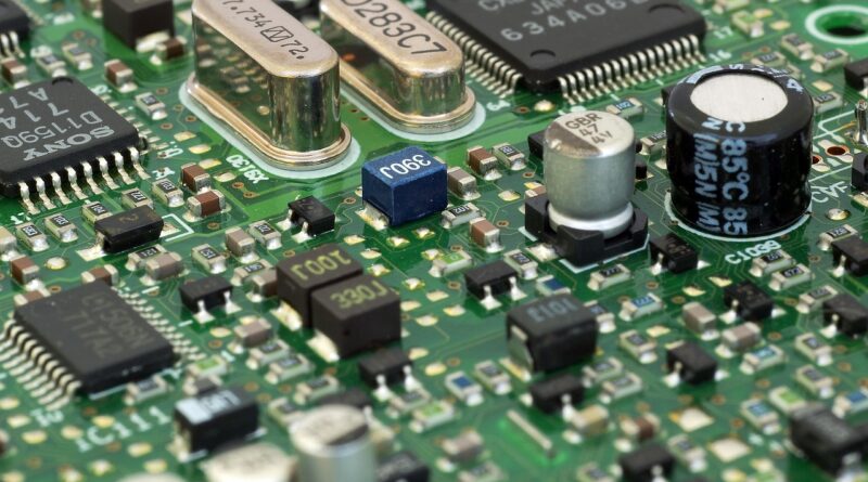
How Do Transistor Current Components Control Modern Electronic Circuits?
Why Do Transistor Current Components Matter in Modern Electronics?
When you choose transistor current components, you decide how a circuit passes current, blocks it, increases it, or follows a signal. That decision shows up in heat, battery runtime, switching speed, noise, and field life when the unit sits in a closed box through summer. For more component selection topics, you can also visit the Components section.
Current Control in Real Products
A transistor is not only a small black package with three pins. On a sensor board, it may pull a relay coil low; in an audio preamp, it may lift a weak microphone signal; in a charger, a power MOSFET may switch several amps thousands of times per second. The use case changes, but the basic point stays the same: a small control signal handles a larger current path.
Switching and Amplification Jobs
For switching, the transistor should sit close to fully off or fully on. For amplification, it works in a middle range, and the output current follows the input signal. All About Circuits describes BJT switching as a case where cutoff and saturation are the main states, not proportional current control. That point helps separate a digital load switch from a small-signal amplifier. (allaboutcircuits.com)
Industry Demand Behind Tiny Parts
The parts are small, but the industry behind them is not. The Semiconductor Industry Association announced on February 7, 2025 that global semiconductor sales reached $627.6 billion in 2024, a 19.1% rise from $526.8 billion in 2023. This number covers broad semiconductor sales, not a clean count of discrete transistors by current class. Even so, it shows why current component selection matters in consumer, industrial, automotive, and power products. (semiconductors.org)
How Does a Transistor Control Current?
A transistor controls current by using one terminal as the command input and two terminals as the main current path. The device physics are not the same for BJTs and MOSFETs, so the datasheet terms are not the same either. Once you know which current is the load current and which signal controls it, the circuit is much easier to read.
Three Terminals Create a Controlled Path
A BJT uses base, collector, and emitter terminals. A MOSFET uses gate, drain, and source terminals. NIST explained in a February 2022 article that, in a typical MOSFET, current travels through a narrow channel between source and drain, and the gate controls how much current flows in that channel. The article also notes that the channel can be about one billionth of a meter thick in modern devices, which is hard to picture, but it explains why small defects matter. (nist.gov)
BJT Base Current Multiplies Load Current
In an NPN BJT used as a low-side switch, the load sits between the positive supply and the collector. The emitter goes to ground. When you feed base current through a resistor, collector current can flow through the load. The current gain, often shown as hFE or beta, tells you how collector current relates to base current under a stated test condition. For a switch, designers usually drive the base harder than the simple gain number suggests, because saturation gain is lower and changes from part to part.
MOSFET Gate Voltage Changes Channel Resistance
A MOSFET works in a different way. The gate draws very little steady DC current, but it has capacitance, so it still needs charge when switching. A high enough gate-source voltage lowers channel resistance and lets drain current flow. Do not treat gate threshold voltage as the full-on voltage. Threshold often means the device has just started to conduct a small test current, not that it can safely run a motor, heater, or LED strip.
Which Current Ratings Should You Read First?
Datasheets can look crowded, and it is easy to pick the largest current number on page one. That shortcut is behind many failed prototypes. Current ratings only make sense with voltage, temperature, duty cycle, package, and board copper. Read these limits together, not as separate wins.
Maximum Current Needs a Temperature Context
Maximum collector current for a BJT or maximum drain current for a MOSFET is usually tied to a temperature condition. A TO-220 MOSFET may look strong in a datasheet table, but the rating may assume the case is held at 25°C. On a small PCB with no heatsink, the usable current can be much lower. If the package is too hot to touch after one minute, that is not a measurement, but it is a warning.
Gain Numbers Need Test Conditions
Take the 2N3904 as a familiar example. The onsemi datasheet lists DC current gain values under specific collector current and collector-emitter voltage test conditions, including a minimum hFE of 100 at IC = 10 mA and VCE = 1 V. The same family is also commonly used around low current signal and switching tasks, not high-current power loads. That small line in the table explains why test conditions matter more than a loose gain label. (onsemi.com)
Voltage, Power, and Heat Share One Limit
A transistor fails when any key limit is crossed. Too much current overheats the die. Too much voltage can break down a junction or oxide. Too much power means current and voltage are both present across the device, which is a problem in linear operation. For a first check, use P = V × I, then compare the heat path with the junction temperature rating. The safe operating area graph is often more useful than the headline current rating.
Should You Choose a BJT or MOSFET for the Load?
The right choice depends on load current, control voltage, switching speed, cost, leakage, and how much voltage drop the circuit can accept. A BJT is still useful in many small circuits. A MOSFET often wins when lower loss is needed at higher current. Neither part fixes a weak layout or a poor driver.
BJTs Suit Small Loads and Simple Analog Gain
Choose a BJT when the current is modest, the control signal can supply base current, and a small saturation voltage is acceptable. Relay coils, indicator LEDs, buzzers, and simple level shifting are common cases. In analog circuits, BJTs also remain common for current mirrors, bias stages, and low-noise front ends. The tradeoff is base current. If your microcontroller pin can only spare a few milliamps, calculate the base resistor and check the forced gain. See also: Gadgets.
MOSFETs Fit Higher Current Switching
Choose a MOSFET when you want low on-resistance and low voltage drop at higher load current. As a public datasheet example, Vishay lists the IRLZ44 power MOSFET with a 60 V drain-source rating and 50 A continuous drain current at VGS = 5 V and TC = 25°C, while the same table shows 36 A at TC = 100°C. Those figures help with part screening, but they do not mean a bare part on a small board can carry 50 A all day. (vishay.com)
Drivers and Protection Parts Finish the Circuit
A current component often needs support parts around it. A BJT needs a base resistor. A MOSFET may need a gate resistor, pull-down resistor, or a gate driver for fast PWM. Inductive loads need flyback protection, such as a diode, TVS diode, or snubber, depending on release speed and voltage limits. A motor starting from rest can draw far more than its running current. A relay coil can kick voltage back into the transistor when switched off. Small support parts save larger parts.
How Can You Size Transistor Current Components without Burning Them?
Good sizing starts with the real load, not the part number. Measure or estimate the worst normal current, then add surge, heat, and supply tolerance. If reliable public data is not available for your exact load, do not make up a number. Use the load datasheet, bench measurements, and a margin that fits the product risk.
Start with Load Current, Surge Current, and Duty Cycle
First write down the load voltage and steady current. Then check what happens at turn-on. A 12 V fan, solenoid, pump, or lamp may draw a short surge. PWM loads add another issue because switching loss rises with frequency and gate charge. A transistor that is fine at 500 mA steady current may run hot if it switches a high-current inductive load at 20 kHz. The duty cycle decides how long heat has to build.
Add a Sensible Derating Margin
For many working boards, choosing a transistor rated well above the measured current costs less than fixing heat problems later. A common shop rule is not to run small components near their absolute maximum ratings. Use those ratings as do-not-cross limits, not normal operating targets. If the load needs 800 mA, a 1 A transistor may work only with mild temperatures and short duty cycles. A 2 A or 3 A part often gives the design more room.
Check Layout, Heat, and Failure Clues
The package and PCB copper are part of the current path. Wide traces, short return paths, and enough copper around a power device reduce voltage drop and heat. Watch for clues during testing: slow turn-on edges, a MOSFET gate stuck halfway, a BJT with too little base drive, or a package that heats even at light load. If the failure looks random, check transients. If it fails after a few minutes, check thermal limits. Different symptom, different root cause.
FAQ
Q1: What Are Transistor Current Components? A: They are transistor parts and related circuit elements that control, switch, or amplify current in an electronic circuit, including BJTs, MOSFETs, resistors, drivers, and protection devices.
Q2: Is a MOSFET Better Than a BJT for Current Switching? A: A MOSFET is often better for higher-current switching because it can have low on-resistance. A BJT can still be simpler for small loads, signal gain, and low-cost control circuits.
Q3: Why Can a Transistor Rated for High Current Still Overheat? A: The headline current rating may depend on case temperature, heatsinking, pulse width, and board copper. If the device cannot move heat away from the die, it overheats at a lower current.
Q4: Can Gate Threshold Voltage Tell You the Usable MOSFET Current? A: No. Gate threshold only shows where the MOSFET begins to conduct a small test current. Use RDS(on), gate-source voltage, thermal data, and safe operating area for load current decisions.
Q5: What Should You Check First in a Transistor Datasheet? A: Check maximum current, voltage rating, power dissipation, gain or on-resistance, thermal resistance, package, and the test conditions behind every number.